
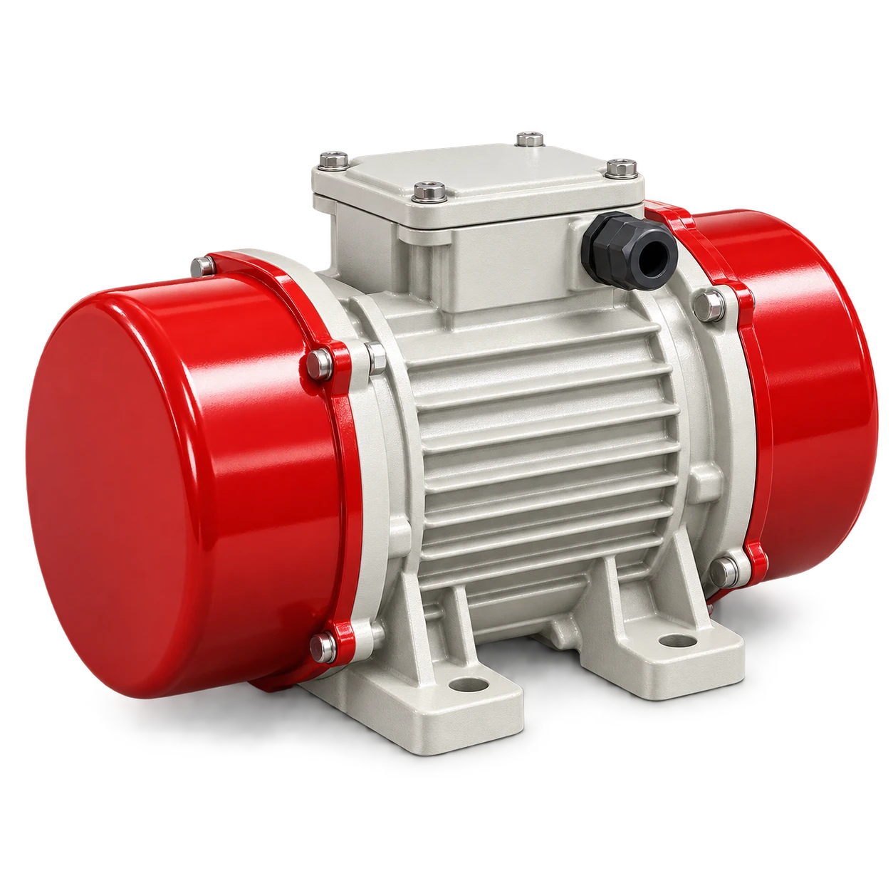
Vibrator motor force adjustment is not a stand-alone dial setting. First verify the motor, mounting plate, fasteners, electrical protection and process objective. Then isolate the equipment, set both shaft-end eccentric weights exactly as the model manual requires, replace the covers, and commission from the lowest effective setting while recording current and material response.
The MVE series vibrator motor is selected from excitation force, speed, power and mounting size. Those catalog fields are quotation inputs, not permission to fit a motor to an unverified hopper or run it at maximum setting. The supporting structure and stored material complete the vibrating system.
Define the process result before changing force
Write an observable target. “Improve flow” is too vague. A commissioning target might be to restore discharge after a defined valve command, maintain a specified feeder inlet condition, clear residue from a chute within an agreed pulse time, or achieve the motion specified by a screen or feeder designer.
Also define stop conditions: line current above the motor nameplate, loose fasteners, cracked welds, abnormal noise, unexpected structural movement, product compaction or no improvement after the approved adjustment range.
Vibration does not correct an undersized outlet or unsuitable hopper geometry. Cohesive powder can arch or form a stable flow channel, while excessive vibration can densify some materials. Review moisture, consolidation time, wall angle, outlet size, valve position and downstream capacity before assigning the entire problem to force setting.
Treat the mount as part of the machine
A rotary vibrator develops cyclic load that must enter the structure through its feet and mounting plate. A flexible, warped or contaminated mounting surface can waste motion, raise local stress and allow bolts to loosen.
The Mooser vibration-motor manual requires a flat, clean and flexurally rigid mounting plate and links improper mounting with broken motor feet. It also specifies checking fastener security after initial operation. Its exact bolt grades, torque values and inspection intervals apply to the models in that manual; use the selected MVE motor documentation for the project values.
Before energizing, record:
| Check | Evidence |
|---|---|
| Mounting location | Approved equipment or structural drawing |
| Plate condition | Flat, clean contact area prepared as the model manual requires |
| Fasteners | Correct grade, size, locking method and model-specific torque |
| Restraint | Secondary retention if required by the manufacturer or risk assessment |
| Cable | Flexible routing, strain relief, earth continuity and no rubbing point |
| Covers | Both eccentric-weight covers fitted and seals undamaged |
Do not weld the support with the motor installed and connected. Follow the equipment and motor manuals for welding, grounding and reinspection.
Understand what the eccentric scale represents
Rotating eccentric mass produces centrifugal force. In simplified form:
F = m × e × ω²
Here, m × e is the unbalance and ω is angular speed. This relationship explains two practical points: weight position changes unbalance, and force changes with the square of speed. It does not provide a safe setting without the motor’s approved data.
The OLI industrial vibrator catalog directs installers to the product manuals and states that electric vibrators need suitable external overload protection. Use the manual for the exact model, supply frequency, permitted speed and weight-setting method.
Do not assume that every stamped percentage means the same thing. On the Martin units documented in its electric vibrator manual, the marked percentage relates to the total force on the nameplate. That convention is useful for understanding, but it must not be transferred to another manufacturer’s motor unless its manual confirms the same scale.
Isolate energy before opening a weight cover
Force adjustment exposes rotating eccentric weights. Stop the driven equipment, isolate all relevant energy sources, apply the site’s lockout/tagout procedure, verify isolation and allow the motor to cool before removing a cover. The U.S. OSHA hazardous-energy guidance explains that lockout/tagout addresses unexpected energization or release of stored energy during servicing; a normal stop command is not equivalent.
The isolation boundary may include the vibrator, associated feeder or valve, upstream material supply, pneumatic devices and stored mechanical energy. If the motor is mounted on a silo or hopper, consider material release and work-at-height hazards as well.
Never run the motor with weight covers removed unless the manufacturer’s controlled test procedure explicitly requires it and the risk controls are in place. Refit covers and seals before the commissioning run.
Make equal, mirror-image weight adjustments
For a common vibrator with eccentric weights at both ends:
- Confirm the exact model and read its manual and nameplate.
- Photograph or mark the as-found position without obscuring factory marks.
- Isolate and verify zero energy.
- Remove both covers using the specified procedure.
- Set the adjustable weights on both ends to the same approved index, arranged as the required mirror images.
- Tighten the weight fasteners to the model-specific value.
- Check free clearance and seal condition.
- Refit both covers.
- Record the setting and responsible technician.
Martin’s manual warns that unequal shaft-end settings produce uneven force. It also recommends using the lowest force that moves the material. This is sound commissioning logic, but the actual adjustment hardware and torque must come from the selected motor’s documentation.
Worked force-setting example
Assume a manual explicitly states that its percentage scale is linear with a 5.0 kN nameplate maximum. At a 40% setting:
nominal centrifugal force = 5.0 kN × 0.40 = 2.0 kN
This is a calculation example, not an MVE specification. Confirm the nameplate force, scale convention and supply frequency for the delivered unit. If frequency changes, do not scale force casually: because speed is squared in the force relationship, an overspeed can create a large load increase. Mooser’s manual specifically warns that operation above nameplate frequency can produce impermissibly high centrifugal force.
Check electrical protection and paired-motor logic
Each motor needs protection selected from its electrical data and applicable code. Record supply voltage and frequency, motor current on each phase, protection settings and trip test evidence. If an overload trips, investigate the cause before resetting it.
When two counter-rotating motors create linear motion, they form one functional set. The Martin and Mooser manuals both require logic that removes power from both if one unit stops, with appropriate protection for each motor. Running one motor alone can impose unintended motion and severe mechanical load.
Verify phase sequence and rotation using the manufacturer procedure. Do not infer correct process motion only from a contactor command or VFD display. If a frequency converter is used, obtain the motor manufacturer’s permitted frequency range and thermal conditions; the fact that a drive can produce a frequency does not mean the vibrator is rated for it.
The screw-conveyor soft-starter and VFD guide gives a broader explanation of why drive capability, motor cooling and mechanical limits need separate checks. Apply the vibrator motor’s own manual rather than copying conveyor settings.
Commission in measured steps
Begin at the approved low setting. Run the shortest useful process test, then stop and inspect. Increase one setting step only if the target is not met and all observations remain acceptable.
Use a commissioning sheet with the material and fill level, valve and downstream state, both weight settings, run duration, line current, fastener witness marks, material response, abnormal noise, and post-run temperature observation using the manufacturer’s method.
Compare like with like. A nearly empty hopper and a full hopper have different mass and flow behavior. Do not credit a new force setting for a result caused by a lower material head or an opened downstream valve.
After the initial operating period, isolate the equipment and inspect fasteners, welds, covers, cable routing and structure according to the manufacturer schedule. The Martin manual calls for checking line current and mounting security after initial use; do not copy its times or torque values to another model without confirmation.
Diagnose a poor result before increasing force
| Observation | Check before increasing force |
|---|---|
| Motor current high | Supply, phase balance, mounting rigidity, weight setting and mechanical damage |
| Loud impact or rattling | Loose plate, bolts, covers, cracked weld or contact with adjacent equipment |
| Motor runs but flow does not improve | Outlet blockage, valve position, material compaction, arching and vibrator location |
| One of a pair trips | Separate overloads, phase current, interlock and mechanical symmetry |
| Fasteners loosen again | Surface flatness, bolt and locking selection, torque procedure and structural flexibility |
| Flow improves only while continuously running | Process design, duty cycle, heat, material compaction and control strategy |
An air fluidization pad is a different flow-aid option for suitable dry powders. It needs clean air, appropriate hopper geometry and a material-specific assessment; it is not an automatic substitute for mechanical vibration.
Conclusion
Vibrator motor force adjustment should finish with the lowest verified setting that meets a defined process target. Correct mounting, equal mirror-image weights, covers, overload protection, paired-motor interlocks, line-current checks and post-run inspection are part of the setting. If flow remains unstable, investigate the material, hopper and outlet system instead of treating higher force as the only answer.
For a quotation, provide the driven structure, material, required process result, proposed mounting, supply frequency and voltage, duty cycle and required excitation range.