
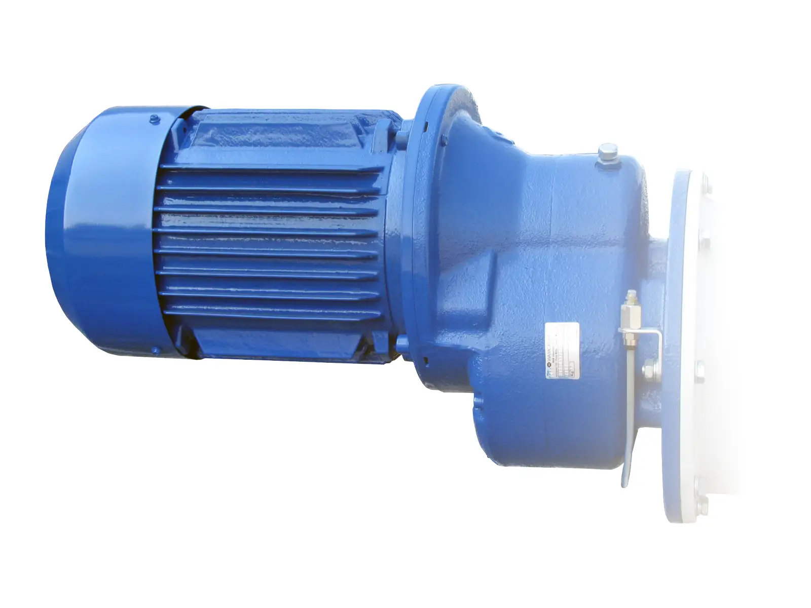
A cement screw conveyor gearbox oil selection should start with the exact reducer nameplate and manufacturer manual. Do not select oil from motor kilowatts, screw diameter, or a generic “heavy-duty gear oil” label. Confirm the reducer model, mounting position, approved lubricant class and viscosity, temperature range, seal compatibility, fill method and service interval as one documented decision.
VOGO’s project-configured cement screw conveyors use application-matched drives, but the project documents must identify the actual reducer and lubricant. The product page does not prescribe a universal oil, fill volume or change interval.
Why the Reducer Manual Governs the Oil Choice
ISO 12925-1:2024 establishes specifications for lubricants used in enclosed gear systems. It provides a useful procurement language, but it does not select one oil for every reducer. Gear geometry, bearing arrangement, pitch-line speed, load, sump temperature, seals and lubrication method differ between products.
The reducer manufacturer has evaluated those details for a defined unit. NORD, for example, publishes a B1000 installation manual, separate oil-quantity information and a gear-unit catalogue. This separation is instructive: catalogue torque data, installation instructions and oil data answer different questions. A purchasing team should obtain all three for the offered reducer revision.
Treat the nameplate and order code as configuration identifiers. Two gearmotors with the same motor power can have different reducer families, ratios, orientations and lubricant requirements. If the manual or order-specific data conflict with a site habit, stop and resolve the conflict with the reducer supplier.
Cement Screw Conveyor Gearbox Oil Selection Workflow
Use this sequence before naming a lubricant on the purchase order or maintenance plan.
- Identify the exact unit. Record manufacturer, reducer type, size, ratio, serial or order number, motor arrangement and output-shaft orientation. Photograph the nameplate and plug locations.
- Confirm the mounting position. Match the installed orientation to the manufacturer’s mounting-position code. Include conveyor inclination and whether the drive is above, below or beside the screw centreline.
- Obtain the approved lubricant table. Record oil type, viscosity grade, approval or product list, permissible temperature range and any restrictions for backstops, brakes or special seals.
- Check the temperature case. Give the supplier the minimum startup ambient, maximum ambient, expected duty cycle, starts per hour and any heat from the conveyed material. Use the manufacturer’s allowable range rather than a plant-wide viscosity rule.
- Confirm quantity and level method. Determine whether the unit is factory filled, which plug is the level point, whether a dipstick or sight glass applies, and the specified condition for checking level. Do not assume a catalogue litre value is a field level target.
- Review compatibility before changing oil. Compare base-oil family, additive system, viscosity and seal compatibility. Matching ISO VG numbers alone does not establish compatibility.
- Define the maintenance evidence. Record fill product, batch, quantity added, operating hours, temperature, leak condition and sample results. Keep the approved substitute list with the asset record.
This workflow is distinct from reducer sizing. The gearbox service-factor guide checks continuous torque, peak torque and thermal capacity; it does not choose or approve a lubricant.
Mounting Position Changes the Oil-Level Question
Reducer oil must reach the intended gears and bearings without excessive churning. Plug functions and the static oil level therefore depend on orientation. A plug that is a breather in one position may not be the correct level point after the reducer is rotated. The required quantity may also change.
This matters on inclined screw conveyors. A layout revision can change the reducer orientation even when the same model, ratio and motor remain. Reusing the previous fill quantity without checking the new mounting-position sheet can result in an incorrect level.
Use the order-specific drawing to mark:
- fill and breather location;
- level plug, dipstick or sight-glass reference;
- drain point and access clearance;
- any expansion tank, oil reservoir or forced-lubrication connection;
- required standstill and temperature condition for the level check.
Do not rotate a breather or swap plugs merely to make access easier unless the manufacturer approves the final arrangement. A breather blocked by cement dust can also affect internal pressure and leakage, so access and contamination control belong in the installation review.
What Viscosity Grade Does—and Does Not—Tell You
Viscosity affects film formation, churning losses and cold-start behaviour, but an ISO viscosity grade is only one part of the lubricant specification. It does not identify the base oil, additive chemistry, material compatibility or manufacturer approval.
For that reason, “ISO VG 220” on two containers does not make the products automatically interchangeable. Mixing incompatible lubricants can change foaming, air release, filterability, deposits or seal behaviour. If the installed oil cannot be positively identified, ask the reducer and lubricant suppliers for a written conversion procedure. That procedure may require draining, cleaning or flushing; do not invent a universal flushing ratio.
The temperature review also needs two limits. First, confirm that the oil supports cold startup at the lowest ambient condition. Second, confirm that the reducer remains within its allowed operating and oil-temperature range at sustained load. A hotter-running reducer is not automatically cured by a higher-viscosity oil: overloading, incorrect level, misalignment, contamination, blocked ventilation or bearing damage may be the cause.
The bearing-temperature monitoring guide explains how to establish comparable operating baselines rather than apply an arbitrary surface-temperature threshold.
Worked Document-Control Example
Assume a project originally specifies a horizontal control-fed conveyor. The purchase record lists one reducer model with a defined horizontal mounting code and a factory fill. During layout coordination, the conveyor is raised to an incline and the gearmotor is rotated to clear a support.
The safe decision is not “same reducer, same oil litres.” The review should compare the original and revised mounting-position codes and ask the reducer supplier to confirm:
| Check | Original record | Revised evidence required |
|---|---|---|
| Reducer identity | Model, ratio and order number | Confirm unchanged or issue a new selection |
| Mounting position | Horizontal code | Supplier-approved inclined/rotated code |
| Oil specification | Factory-fill product | Confirm approved type and viscosity remain valid |
| Oil quantity | Order-specific value | New order-specific quantity or level procedure |
| Plug arrangement | Marked on drawing | Revised fill, level, drain and breather positions |
| Thermal duty | Original load case | Recheck sustained load and ambient conditions |
This is a selection scenario, not VOGO test data. The result may be the same oil with a different quantity, a changed plug arrangement, an auxiliary oil device, or a different reducer. Only the reducer supplier can close that configuration decision.
If the screw inlet sits continuously flood loaded beneath a silo, classify it as a screw feeder. Its head load and worst loaded restart may raise reducer load and oil temperature. The inlet may need increasing or variable pitch, tapered outside diameter or a justified mass-flow design. Lubricant selection cannot correct arching, rat-holing, poor outlet geometry, moisture or compaction.
Fill, Commissioning and Troubleshooting Checks
Before opening the reducer, stop material feed, allow moving parts to stop, isolate every hazardous energy source and control stored material or pressure. OSHA’s hazardous-energy guidance explains why a stop command is not an energy-isolation procedure.
For commissioning, verify the unit is in its approved mounting position and that shipping closures have been replaced or configured as instructed. Check the oil level by the manufacturer’s method. Record any addition; “topped up” is not an auditable quantity. Inspect for leakage before load, after initial operation and after the first planned shutdown.
Use symptoms as investigation triggers, not as oil diagnoses:
| Observation | Check before changing oil |
|---|---|
| Foaming or oil at breather | Correct level, approved oil, mixed products, water, breather location and agitation |
| Rising temperature | Load, mounting position, oil level, ambient, ventilation, alignment and bearing condition |
| Persistent leak | Overfill, blocked breather, seal condition, shaft runout and internal pressure |
| Dark or hazy sample | Operating hours, water, dust, wear debris, oxidation indicators and trend against prior samples |
| Noise after oil change | Correct product, level, contamination, rotation, alignment and mechanical damage |
Do not drain a serviceable oil merely because colour differs from a previous brand. Conversely, a clear appearance does not prove acceptable viscosity, cleanliness or additive condition. Use repeatable sampling points and laboratory methods agreed with the reducer or lubricant supplier when condition-based intervals are required.
Procurement and Handover Checklist
Require these items with the drive package:
- reducer manufacturer, full type code, ratio, serial/order number and mounting position;
- continuous, peak and thermal ratings for the stated duty;
- approved oil type, viscosity, temperature limits and named factory fill;
- fill quantity or level-check method for the delivered orientation;
- plug and breather drawing with safe service access;
- oil-change interval and the conditions that shorten it;
- written compatibility or conversion instructions for approved substitutes;
- seal, backstop and auxiliary-lubrication restrictions;
- commissioning record and oil-maintenance log template.
For the conveyor application, also provide material condition, control-fed conveyor or flood-loaded feeder classification, inclination, screw speed, loaded-stop dwell, starts per hour and worst restart case. An enclosed screw casing is not automatically airtight or pressure rated, and the reducer lubricant does not establish either property.
Conclusion
A sound cement screw conveyor gearbox oil selection is an order-specific engineering record. Start with the exact reducer and mounting position, then confirm the manufacturer’s approved oil, viscosity, temperature limits, compatibility, fill method and interval. Recheck the decision whenever orientation, duty or lubricant changes, and use measured condition trends rather than appearance or a generic plant rule.
Send VOGO the reducer preference, mounting position, environment and duty data to coordinate the drive-package documentation.