
Screw feeder vs screw conveyor: key design differences and selection guide
Non-specialists often use the terms “screw feeder” and “screw conveyor” interchangeably in cement and bulk material handling. In engineering, they are distinct machines with different operational duties. Both utilise the Archimedes principle, where a helical blade wound around a central shaft pushes material forward, but modern designs are built for specific tasks. Using the wrong equipment can cause mechanical failures such as motor burnout and shaft fractures, which lead to plant downtime. Furthermore, the rheological properties of fine powders—such as aeration, compressibility, and shear strength—dictate how material interacts with the helical blade. Ignoring these physical characteristics during the specification phase inevitably leads to severe operational inefficiencies. Process engineers and mechanical designers in concrete batching or dry-mix mortar facilities need to recognise these differences to select the correct equipment for cement, fly ash, and dry powders, ensuring both volumetric accuracy and mechanical reliability.
Flooded vs controlled inlet
Screw feeders and screw conveyors differ mainly in their inlet conditions and operational purpose. A screw feeder meters and controls the flow of bulk materials. It mounts directly beneath a storage vessel such as a hopper, bin, or silo. The inlet of a screw feeder is always 100 per cent flood loaded. The discharge rate depends on the feeder’s design parameters and rotational speed. It is an active, volumetric metering device. When dealing with highly aeratable materials like fly ash, a feeder must also manage de-aeration to prevent flooding past the discharge point. Variable speed drives (VSDs) are typically integrated with the feeder to adjust the rotational speed dynamically, ensuring the mass flow rate aligns precisely with the downstream process demand.
A standard screw conveyor transports material. Its inlet receives controlled material, usually from another feeder or conveyor. The discharge volume is proportional to this controlled infeed. If the infeed is insufficient, the conveyor runs partially empty. If the feeder restricts output, it cannot meet the process demand. A conveyor relies on external flow control, while a feeder provides it. Conversely, a conveyor operating under a flooded inlet would experience uncontrolled surging, rendering any downstream weighing or dosing system entirely ineffective. In concrete batching, where cement or fly ash is transferred from a silo to a weighing hopper with high accuracy, this difference determines the control strategy.
Structural and design divergences: heavy-duty vs. light-duty
The structural designs of feeders and conveyors differ to handle different mechanical loads. A screw conveyor handles a uniform, controlled load along its entire length. It typically has a standard, constant pitch and a lighter central shaft because the torsional and bending loads are predictable and moderate. In contrast, a screw feeder extracts material from a flood-loaded condition. This generates high starting torque and continuous high radial loads. To withstand these forces, feeders have heavy-duty shafts, heavy end bearings, and reinforced flighting. To manage the immense torsional stress, feeder shafts are often sized with a higher safety factor, sometimes utilising solid shafts or thick-walled seamless steel pipes rather than the thinner welded tubes found in conveyors.
To prevent material rat-holing or bridging above the inlet, screw feeders often use variable pitch designs, tapered outside diameters, or mass flow configurations. This increases the available volume progressively as the material moves towards the discharge and allows even extraction across the entire hopper outlet. Additionally, feeders may incorporate specialised flighting configurations, such as ribbon flights for sticky materials or cut-and-folded flights to gently mix and de-aerate powders. The trough clearances in a feeder are also kept to an absolute minimum to prevent fine particles from bypassing the flights and accumulating in the dead zones. A standard conveyor lacks these specialised extraction features, so it cannot effectively draw down material from a silo without causing flow irregularities.
Severe consequences of misapplication
Using a standard screw conveyor as a feeder to save capital expenditure is a common mistake in plant design. Mounting a conveyor directly under a silo subjects it to flood loading. The equipment must then handle bulk material beyond its design capacity. Fine, dry powders like cement and fly ash aerate and pack under the continuous shear of an improperly designed screw. The standard pitch and lighter shaft cannot break out compacted material from a dead state. These conditions result in high torque spikes. Frequent outcomes include motor burnout from sustained overloading, sheared shafts from torsional stress, and damaged hanger or end bearings.
Consider a practical case where a standard conveyor is retrofitted under a 100-tonne cement silo. Within weeks, the constant flood loading causes the cement to compact at the trough bottom. The conveyor motor, lacking the necessary breakaway torque, trips on overload during startup after a weekend shutdown. Maintenance teams are forced to manually clear the compacted cement, exposing them to silica dust and confined space hazards. This scenario highlights how a seemingly minor capital saving during procurement translates into significant health, safety, and operational liabilities over the asset’s lifecycle. In high-duty applications, these failures halt production and cause secondary damage to the trough and drive components. The cost of replacing a failed conveyor and managing unplanned downtime exceeds the initial savings of specifying the correct equipment.
Selection matrix for cement, fly ash, and dry powders
Selecting equipment depends on the process duty. To extract and precisely meter material from a silo into a weighing hopper, a dedicated screw feeder is required. To transfer metered material horizontally or on a slight incline between process stages, a screw conveyor is appropriate. Accurate capacity calculation requires more than just volumetric displacement. Engineers must account for the material’s bulk density, which can vary significantly depending on the degree of aeration and compaction within the silo. The angle of repose and the internal friction angle of the specific powder dictate the required trough fill level and the necessary power rating. For instance, highly aerated fly ash may exhibit a bulk density as low as 0.8 t/m³ when fluidised, but can compact to over 1.2 t/m³ at rest. The selection matrix must therefore incorporate a suitable safety margin for motor power to handle these transient density peaks without stalling.
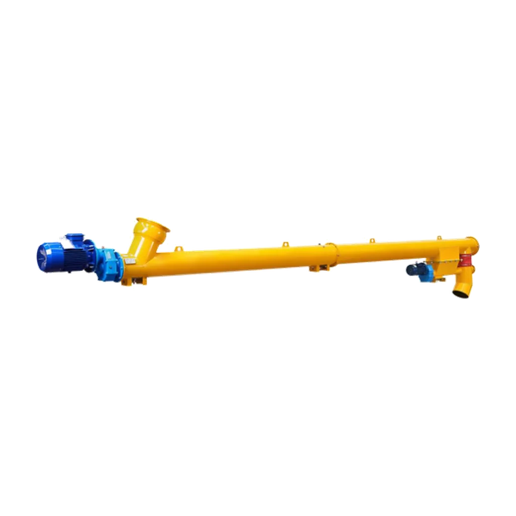
The VOGO Machine Cement Screw Conveyor is a tubular screw conveyor for enclosed powder conveying and controlled feeding. Available in diameters of Ø89 mm to Ø407 mm, the rigid tubular body keeps the conveying path compact and limits dust exposure. These units are tailored to the project. Drive, bearing, and connection arrangements match the material and throughput requirements. Selectable hanger and end bearings allow for long term maintenance.
Catalog reference capacities are 1.3 to 170 t/h, but actual output depends on bulk density, moisture, and inclination. Output must be confirmed for each project. Proper specification requires material characteristics, required throughput, centreline length, and power supply. Configurations must match the specific duty, such as horizontal transfer in an asphalt plant or inclined feeding in a building materials facility. Start frequency and process temperature are also required to finalise the design.
Drive mechanisms and torque control
The drive assembly further illustrates the divergence between feeding and conveying duties. Screw feeders require drives capable of delivering high breakaway torque to initiate movement from a static, compacted bed of material. Direct-coupled helical gearboxes with high thermal capacity are standard, often paired with variable frequency drives (VFDs) to allow precise speed modulation for accurate volumetric dosing. Torque limiters or shear pins are frequently installed to protect the gearbox and shaft from catastrophic damage if an uncrushable foreign object enters the trough. In contrast, screw conveyors typically utilise standard induction motors with fixed speeds or simple VFDs, as their primary requirement is maintaining a steady transport velocity rather than managing extreme starting loads or providing micro-dosing accuracy. The electrical control architecture for a feeder is inherently more complex, requiring continuous feedback loops to integrate with the plant’s distributed control system (DCS) for automated batching.
Conclusion
Ultimately, the distinction between a screw feeder and a screw conveyor is a fundamental engineering boundary that dictates the reliability of the entire material handling system. Feeders are heavy-duty, flood-loaded metering devices engineered for precision extraction and flow control. Conveyors are lighter-duty transport mechanisms that require a controlled, consistent infeed to operate efficiently. Selecting the correct equipment prevents mechanical failures, ensures dosing accuracy, and maintains optimal material handling efficiency in cement and powder systems. When specifying machinery for concrete batching, asphalt plants, or dry-mix mortar facilities, engineers must rigorously match the mechanical design to the required duty to avoid costly misapplications. Operating each machine strictly within its mechanical and operational limits extends equipment lifespan, reduces maintenance overheads, and maintains process accuracy. For selection parameters and technical specifications, visit the VOGO Machine Cement Screw Conveyor product page or download the official datasheet.