
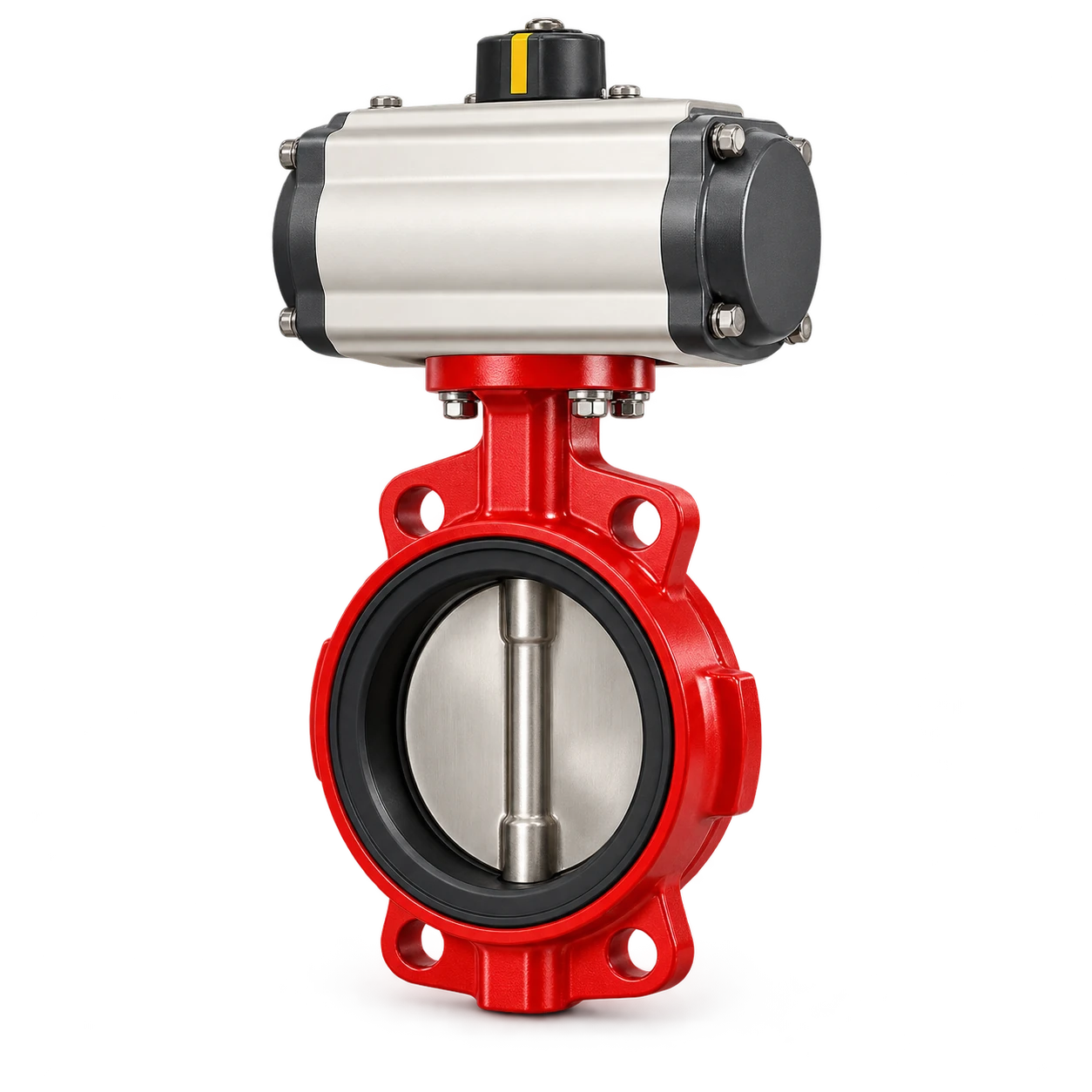
Butterfly valve actuator torque sizing requires matched valve and actuator data. Obtain the valve torque curve for the exact size, seat, media, temperature and maximum differential pressure; apply the project-approved margin; then verify actuator output through the full 90-degree stroke at the lowest credible utility supply. Finally confirm the stem, coupling, bracket and controls can carry and deliver that torque.
The water butterfly valve is selected by pipe size, working pressure and actuation requirement. Those catalog inputs identify the valve option, but they do not provide a universal actuator torque. The delivered valve and actuator suppliers must confirm the final combination for the project conditions.
Build the butterfly valve actuator torque sizing basis
Start with an application sheet rather than an actuator catalog. Record:
- valve manufacturer, series, nominal size and pressure class;
- body, disc, stem and seat materials;
- normal and maximum upstream/downstream pressures;
- maximum differential pressure in either direction;
- fluid, solids content, temperature and cleaning chemicals;
- on/off, isolating or throttling duty and expected cycles;
- required open, close or fail position;
- minimum and maximum air pressure, voltage or hydraulic pressure;
- ambient conditions, enclosure and hazardous-area requirements;
- maximum permitted closing time and water-hammer constraints.
The AWWA summary of ANSI/AWWA C504 shows that a water-service butterfly-valve standard has defined scope limits for media, temperature, sizes and construction. Do not claim that a VOGO valve complies with C504 unless the supplied documentation says so. Use the standard required by the contract and verify the selected valve’s stated ratings.
Compare every governing torque point
A butterfly valve does not present one constant load. The actuator may need to overcome high seat friction as motion begins, a different hydrodynamic load while the disc is in flow, and seating torque near closure. Project terminology varies, but a useful comparison separates:
| Torque point | Meaning | Why it can govern |
|---|---|---|
| Breakaway | Torque to start opening from the seated position | Seat friction, deposits and time at rest |
| Running | Torque while the disc moves through the flow | Differential pressure and disc hydrodynamics |
| End-to-open | Torque near the open stop | Flow load and mechanical stop setting |
| Seating | Torque required to reach specified closure | Seat compression and shutoff requirement |
Obtain these values from the valve supplier for the stated conditions. Do not calculate final torque from nominal pipe pressure and disc diameter alone. That omits seat design, bearing friction, seal condition, flow direction and material buildup.
Likewise, read the actuator curve rather than its largest advertised number. Rack-and-pinion and scotch-yoke units can have different output profiles. Spring-return output also changes through the stroke and differs between air and spring directions. Align the valve demand points with the actuator positions that must satisfy them.
Size at the minimum available supply
For a pneumatic unit, use the minimum pressure available at the actuator while the plant is under peak demand. Compressor discharge pressure is not enough. Include regulator setting, filter loss, tubing, solenoid capacity, elevation and simultaneous users.
Bray’s actuator sizing application asks for the valve series, valve size, service factor and actuator configuration. That structure reinforces the correct workflow: match a defined valve demand to a defined actuator, rather than choosing only by valve diameter. Its output applies to Bray combinations; use the selected suppliers’ data for a VOGO project.
For an electric actuator, confirm output torque across the specified voltage tolerance and duty. Check starting current, motor protection, thermal rating, travel switches, torque switches and manual override. An electric actuator that reaches the position once may still be unsuitable for frequent cycling or a stalled valve.
Apply margin once and document it
The sizing factor must come from the valve/actuator supplier, project specification or responsible engineer. It accounts for expected variation; it is not a license to ignore missing valve data. Avoid stacking several undocumented factors until an oversized actuator results.
Worked selection example
Assume the valve supplier provides the following maximum demand for a defined water duty:
- breakaway torque: 120 N·m;
- maximum running torque: 80 N·m;
- seating torque: 105 N·m.
If the approved sizing factor is 1.25:
required breakaway output = 120 × 1.25 = 150 N·m
required running output = 80 × 1.25 = 100 N·m
required seating output = 105 × 1.25 = 131.25 N·m
Select an actuator whose documented output at the corresponding stroke positions exceeds each requirement at minimum supply. Do not accept an actuator merely because its peak torque exceeds 150 N·m. These figures are a calculation example, not VOGO valve data or a recommended service factor.
Then check the maximum actuator output at the highest supply pressure. The valve stem, key, coupling, bracket and mounting fasteners must tolerate it. An oversized actuator can damage a valve before its own torque limiter or relief device operates.
Verify the mounting interface separately
ISO 5211:2026 specifies part-turn actuator attachment dimensions, driving-component dimensions and reference torque values for interfaces. This supports interchangeability, but it does not complete application sizing.
Confirm all of these items on the certified drawings:
- flange designation and bolt pattern;
- stem square, key or other drive geometry;
- coupling engagement and material;
- bracket stiffness and alignment;
- permitted interface torque;
- clockwise/counter-clockwise action;
- mechanical stops and disc position;
- access for manual override and maintenance.
Avoid using a coupling to correct visible misalignment. Side load can raise operating torque and wear the stem or actuator bearings. Cycle the assembled valve before installation where the acceptance plan permits, then repeat functional testing after pipe installation.
The related cement butterfly valve handles a different dry-powder duty. Do not transfer its actuation assumptions to water service: media, seals, buildup, pressure boundary and failure consequences differ.
Choose fail action from the process hazard
Fail-open and fail-close are process decisions, not actuator defaults. Consider loss of air or power, upstream pump behavior, overflow, contamination, downstream demand, trapped pressure and safe maintenance. A double-acting pneumatic actuator normally stays where forces leave it after air loss unless a separate stored-energy or backup system changes that response.
If spring return is required, verify both directions:
- air torque must move against the spring and valve load;
- spring torque must move the valve to its safe position at the worst process load;
- spring end torque must still complete seating or opening;
- the valve and mounting must tolerate maximum output.
Closing speed matters in water systems. Faster is not automatically safer; rapid closure can create damaging transients. Coordinate actuator volume, solenoid flow and speed controls with the hydraulic analysis. Do not use a needle valve setting as the only protection against water hammer when the system needs engineered surge control.
Test the assembled valve-actuator package
A practical factory and site acceptance record includes:
| Test | Evidence |
|---|---|
| Identification | Valve and actuator tags match datasheets and drawings |
| Stroke | Full open/close without binding; correct indication |
| Minimum utility | Successful operation at specified minimum air pressure or voltage |
| Fail action | Verified result after simulated loss of utility where safe |
| Cycle time | Measured open and close times under stated conditions |
| Stops and switches | Position indication agrees with actual disc position |
| Leakage | Test method and acceptance criterion from the contract |
| Interlocks | Pump and process permissives act in the specified sequence |
Use representative differential pressure if the acceptance procedure requires it; a no-load bench cycle cannot prove the operating torque margin. Trend travel time and actuator pressure or motor current after commissioning. A gradual increase can indicate seat damage, deposits, misalignment or a utility problem.
Servicing an automatic valve can expose stored pressure, actuator springs and unexpected remote commands. OSHA’s hazardous-energy guidance distinguishes energy isolation from a normal stop signal. Isolate the fluid, depressurize the line and actuator, block stored movement and follow the site’s lockout/tagout procedure before removing the actuator or coupling.
Conclusion
Butterfly valve actuator torque sizing is a curve-to-curve and condition-to-condition check. Use verified breakaway, running and seating torque for the exact valve duty; apply one approved margin; compare actuator output at minimum supply through the whole stroke; and protect the stem and ISO 5211 interface from maximum output. Finish with fail-action, cycle-time and assembled-package tests.
For a quotation, provide the fluid, temperature, line and valve size, pressure and maximum differential pressure, materials, fail action, minimum utility supply, cycle time, controls and applicable valve standard.