Introduction
When conveying dense powders such as cement, the structural integrity of the conveyor housing is as important as the rotating assembly. Engineers typically focus on shaft design, flight metallurgy, and drive sizing, which often leaves trough deflection as an overlooked failure mode. Trough deflection occurs when the conveyor housing sags or distorts under the weight of the material load and internal components. This deformation reduces the internal clearances needed for correct operation. This article analyses the root causes of trough deflection in heavy-duty screw conveyors and provides engineering guidelines for structural reinforcement, thickness selection, and maximum span calculations to maintain system reliability and minimise maintenance. Addressing trough deformation during the design stage is more cost-effective than correcting alignment issues during commissioning, and it keeps mechanical components within their design parameters.
Root causes of trough sagging and deformation
Trough deflection results from mechanical loading, environmental conditions, and design compromises. The material load is the main factor. Conveying materials with high bulk density, like cement or fly ash, exerts high downward pressure on the trough floor. Over long distances, this uniform distributed load can exceed the yield strength of the trough plate if the structural section modulus is insufficient.
The physical characteristics of the conveyed material also affect the load profile. Cement and fly ash can compact if the conveyor stops while fully loaded, which creates a higher static load on restart. This settled material exerts high pressure on the trough floor and worsens existing structural weaknesses.
Thermal stresses also affect the trough. When the conveyed material or ambient environment experiences large temperature fluctuations, the trough expands and contracts. If the trough is rigidly fixed without adequate allowance for thermal growth, or if temperature gradients exist across the structure, internal stresses can cause bowing or localized deformation.
Inadequate support spans are another common design flaw. The deflection of a beam, or in this case the trough, is proportional to the fourth power of the unsupported span length. Even a slight increase in the distance between support stands can cause a disproportionate increase in sagging, especially when the trough is fully loaded.
Impact of trough deflection on system integrity
A deformed trough causes more than cosmetic misalignment. The immediate result is lost shaft and flight concentricity. As the trough sags, the internal clearance between the rotating flight and the trough wall becomes asymmetrical. On the lower side of the sag, the clearance decreases and causes mechanical rubbing. This friction accelerates wear on the flight edges and trough liner. It also increases the overall torque requirement and can cause motor overloads.
Trough deflection imposes parasitic radial loads on the end and hanger bearings. Bearings are designed for specific axial and radial forces in a perfectly aligned system. When the trough bends, the bearing housings move out of alignment. This causes uneven load distribution across the rolling elements. The misalignment accelerates bearing fatigue and increases operating temperatures, which shortens component life. Minor trough deformation can lead to mechanical failure. The increased friction generates heat. This degrades lubricants in the hanger bearings and wears the seal faces.
Trough deformation also compromises seal integrity. Shaft seals at the end bearings require a precise, concentric running surface. The misaligned bearing housing forces the seal faces to operate at an angle. This causes rapid seal wear and dust leakage. Contaminants can also enter the system, which is a problem in enclosed powder conveying systems that require strict dust containment.
Structural reinforcement and stiffening strategies
Preventing trough deflection requires careful structural design. U-trough conveyors have an open profile with lower torsional and bending rigidity than closed sections. Weld external stiffeners to the trough exterior to prevent sagging. Fabricate these stiffeners from flat bar or angle iron. Space them at regular intervals directly above the support stands to transfer the load to the foundation. When welding stiffeners, avoid excessive thermal distortion in the trough. Avoid continuous welding. Intermittent stitch welding transfers the load and reduces the risk of warping the trough plate.
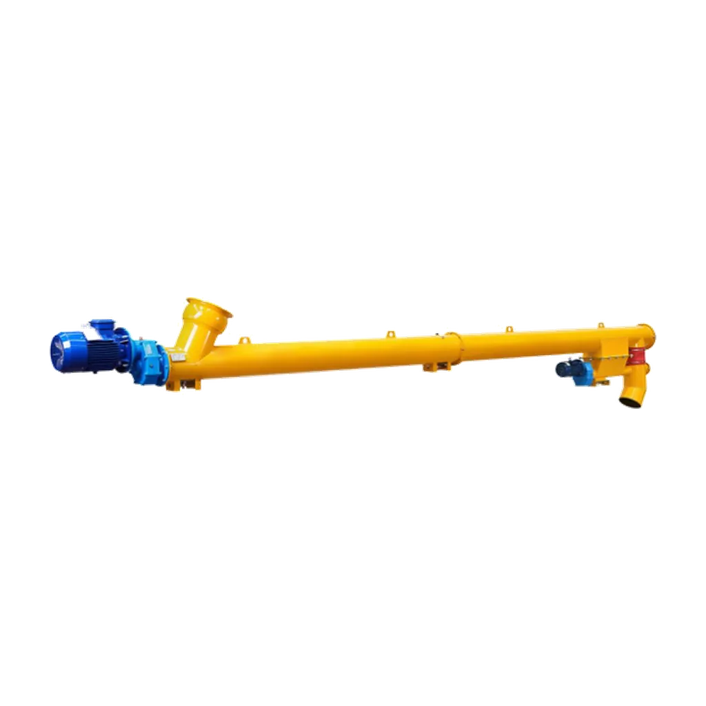
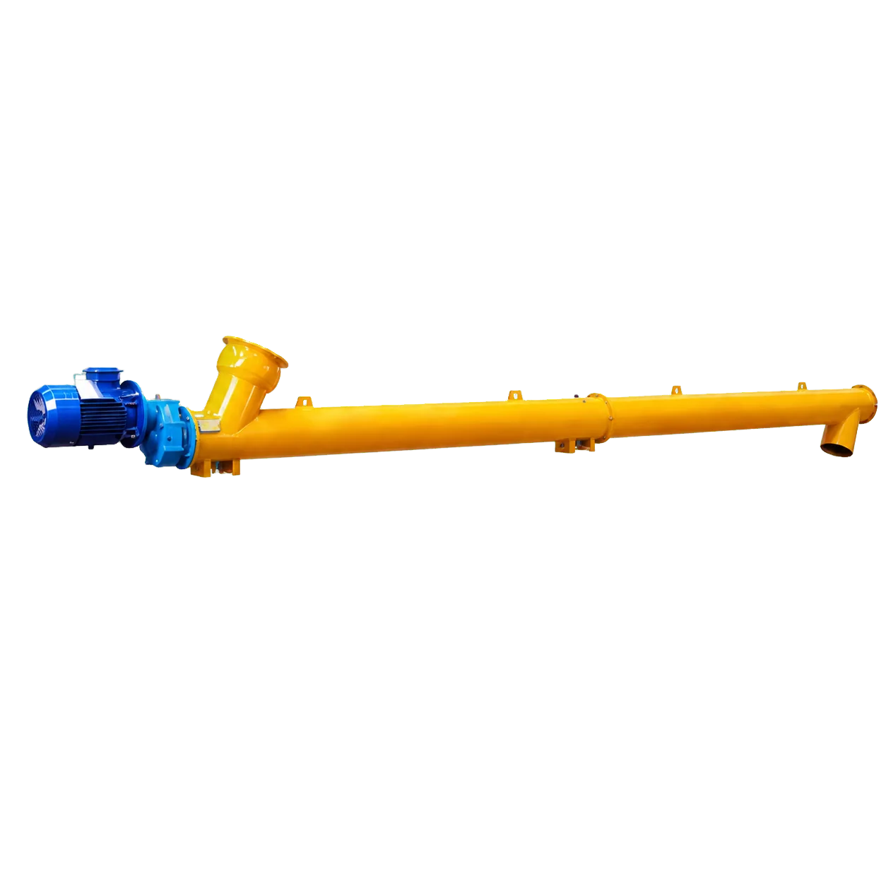
Trough plate thickness is another important factor. Standard thicknesses work for light-duty applications, but heavy-duty cement handling requires thicker plates to resist bending moments. Increasing plate thickness adds weight and cost. A tubular (pipe) design is more efficient. A rigid tubular body has higher structural stiffness and torsional resistance than an open U-trough. The closed circular cross-section distributes stresses evenly and resists deflection under heavy material loads.
Support the trough properly at all flanged connections. Flanges are not designed to bear the bending moments of the trough. They are only for sealing and joining. Position support stands close to flanges to prevent them from acting as unsupported cantilevers.
Calculating maximum support spans
Calculating the maximum allowable span between support stands is required for conveyor design. Deflection increases with the fourth power of the span length, so reducing the unsupported distance is the most effective way to control sagging. The calculation must account for the weight of the empty trough, the screw assembly, and the maximum material load.
Industry standards from the Conveyor Equipment Manufacturers Association (CEMA) provide general guidelines for maximum span lengths based on trough diameter and loading conditions. These are baseline references. Specific projects require a detailed structural analysis. This involves calculating the bending stress and maximum deflection to keep both within acceptable limits. Typically, deflection should not exceed a fraction of the span length (e.g., L/360 or stricter for precision applications).
When long centreline lengths are unavoidable, the design must include intermediate supports. For tubular screw conveyors, support cradles or hanger brackets must allow for axial thermal expansion while restricting vertical and lateral movement. The design must also account for dynamic forces alongside static loads. Screw rotation, material impact at the inlet, and drive unit vibration create dynamic loading on the trough. Support stands need mounting hardware to dampen these vibrations and prevent resonance, which can accelerate fatigue failure in the trough. The foundation or support steelwork must also be sufficiently rigid; a stiff trough on flexible steelwork will still deflect.
Conclusion
Preventing trough deflection maintains shaft concentricity, extends bearing life, and preserves seal integrity in heavy-duty screw conveyors. Plant designers and maintenance managers reduce unplanned downtime and maintenance costs by addressing the root causes of sagging and reinforcing the structure. Specifying equipment for concrete batching or dry-mix mortar production requires a conveyor with structural rigidity. VOGO Machine’s cement screw conveyors use a rigid tubular body. This design keeps the conveying path compact, limits external dust exposure, and resists deflection. Visit the product page or download the datasheet to check selection diameters, length coverage, and configuration options.