
Introduction
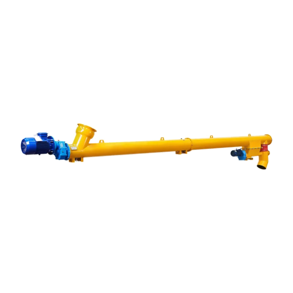
In bulk material handling for cement and dry powders, engineers often judge screw conveyor efficiency by its core mechanical components. However, overall performance depends on the inlet and outlet. A screw conveyor uses a helical flight to push material through a trough or enclosed tube. If material cannot enter smoothly or exit without restriction, the system loses capacity, wears out faster, and experiences downtime.
Proper inlet and outlet design increases capacity, reduces wear, and maintains dust-tight operation in cement and powder systems. For fine, aeratable, or cohesive materials like cement, fly ash, or mineral fillers, poor inlet geometry causes inadequate trough loading. Poorly configured outlets cause bridging, rat-holing, or material spillage. Designing these transition points requires specific engineering principles to maintain reliable bulk solid handling and environmental control.
Inlet geometry and trough loading efficiency
The inlet connects bulk solid gravity flow or mechanical feeding to the screw flight. The goal of inlet design is uniform trough loading. Uneven material entry creates localised stress on the screw shaft and flight, which causes premature mechanical fatigue and increases power consumption.
For most free-flowing dry powders and granular materials, a rectangular or square inlet opening works better than a round drop. A rectangular slot aligned with the screw axis distributes material evenly across the flight width. As an engineering rule of thumb, the inlet width should be at least 1.5 to 2 times the screw diameter. This provides sufficient cross-sectional area for material entry. It prevents arching at the entry point and maintains the volumetric capacity of the first few flight pitches.
Inlet location is also important. Position the inlet to connect directly with upstream equipment such as a rotary valve, a silo discharge flange, or a weigh hopper. In horizontal or slightly inclined conveyors, place the inlet close to the drive end so the screw engages the material along its full length. This increases conveying capacity. In feeder applications requiring controlled metering, the inlet must pair with variable pitch flights or specialised feed hoppers. This controls the drawdown rate and prevents flood feeding.
Overcoming flow challenges with advanced hopper design
Discharge problems in bulk solids handling rarely start in the conveyor tube. They usually begin in the hopper or bin feeding the inlet. When handling difficult, cohesive, or poorly flowing materials, conventional hoppers that narrow into a small outlet often fail. This causes arching, rat-holing, and irregular mass flow. The inconsistent feeding starves the screw conveyor, creating pulsating motor loads and inaccurate batching.
An inverted hopper solves these flow problems. Unlike a traditional funnel-shaped hopper, the inverted design receives material in a wide upper section and has a lower section that widens or remains broad. This geometry distributes the bulk solid more evenly across the inlet slot instead of forcing it into a single narrow point. Inverted hoppers promote mass flow and eliminate the stagnant zones that cause rat-holing. The result is a steady, predictable feed into the screw conveyor.
For highly cohesive materials or applications requiring precise extraction from large storage silos, the inlet design can include mechanical agitation. Simple gravity-fed inlets work for free-flowing cement, but sticky or compacted powders need hopper vibrators, fluidising pads, or live-bottom screw feeders integrated directly above the main conveyor inlet. These active flow devices break up minor arches and deliver a consistent volumetric feed to the screw conveyor. This maintains stable trough loading and prevents mechanical overload.
Alignment, sealing, and dust tight operations
Physical installation and alignment of the inlet and outlet connections are essential in enclosed powder conveying systems. Misalignment between the upstream discharge flange and the conveyor inlet creates gaps in the system. In cement and fly ash transfer applications, even microscopic gaps cause dust emissions. This creates environmental hazards and requires costly cleanup.
Precise alignment centers the inlet directly over the screw flight. An offset inlet causes material to pile up on one side of the trough. The screw then works asymmetrically. This uneven loading accelerates wear on the hanger bearings, end bearings, and trough liner, and reduces overall conveying efficiency. Installers use laser levels and precision machined connection flanges to achieve correct alignment during installation.
The rigid tubular body of a screw conveyor keeps the conveying path compact and limits external dust exposure. Maintaining this seal requires gaskets, flexible connections, and proper bolt torque sequences at the inlet and outlet interfaces. Flexible connections help when the screw conveyor feeds into or discharges from a vibrating weigh hopper. They isolate mechanical vibration from the conveyor tube and maintain a continuous, sealed path for the material and displaced air.
Outlet configurations and discharge control
The outlet design controls how material leaves the conveyor and enters the next process. A poorly designed outlet causes material to back up inside the conveyor tube, resulting in blockages, motor overloads, and shaft failure. Standard horizontal conveyors typically use a drop-through opening at the end of the trough. Multi-discharge applications use intermediate drop-through openings.
For intermediate discharges, size and space the drop-through outlets correctly. An undersized outlet creates a bottleneck that accumulates and compacts material in the downstream trough. Position multiple outlets so the remaining material flows without excessive dragging or aeration. Reversible conveyors alternate the inlet and outlet at both ends of the tubular body based on process routing.
The transition chute or spout connecting the conveyor outlet to a downstream silo or receiving bin must exceed the material’s angle of repose. This maintains gravity-driven flow without relying on the conveyor’s mechanical push. In dust-sensitive environments, the outlet connection must accommodate venting. Material displaces air when entering a receiving vessel, so route that air back through a vent pipe to the conveyor inlet or a dedicated dust collector. Inadequate air displacement design causes pressure buildup, which blows dust past the outlet seals and disrupts powder flow.
Conclusion
Designing screw conveyor inlets and outlets affects system capacity, reliability and environmental compliance. Engineers must select the correct inlet geometry for uniform trough loading and use inverted hoppers for materials with difficult flow characteristics. Transition points must match the specific properties of the bulk solid. Correct alignment, dust seals and properly configured discharge chutes prevent mechanical failures, downtime and maintenance delays. These design principles keep concrete batching, dry mix mortar and ash handling systems within their operating limits. For specific project configurations such as diameter selection, length coverage and custom connections, review the detailed selection parameters for the VOGO Machine cement screw conveyor on the product page or download the official datasheet.
For detailed specifications, visit the cement screw conveyor product page.