
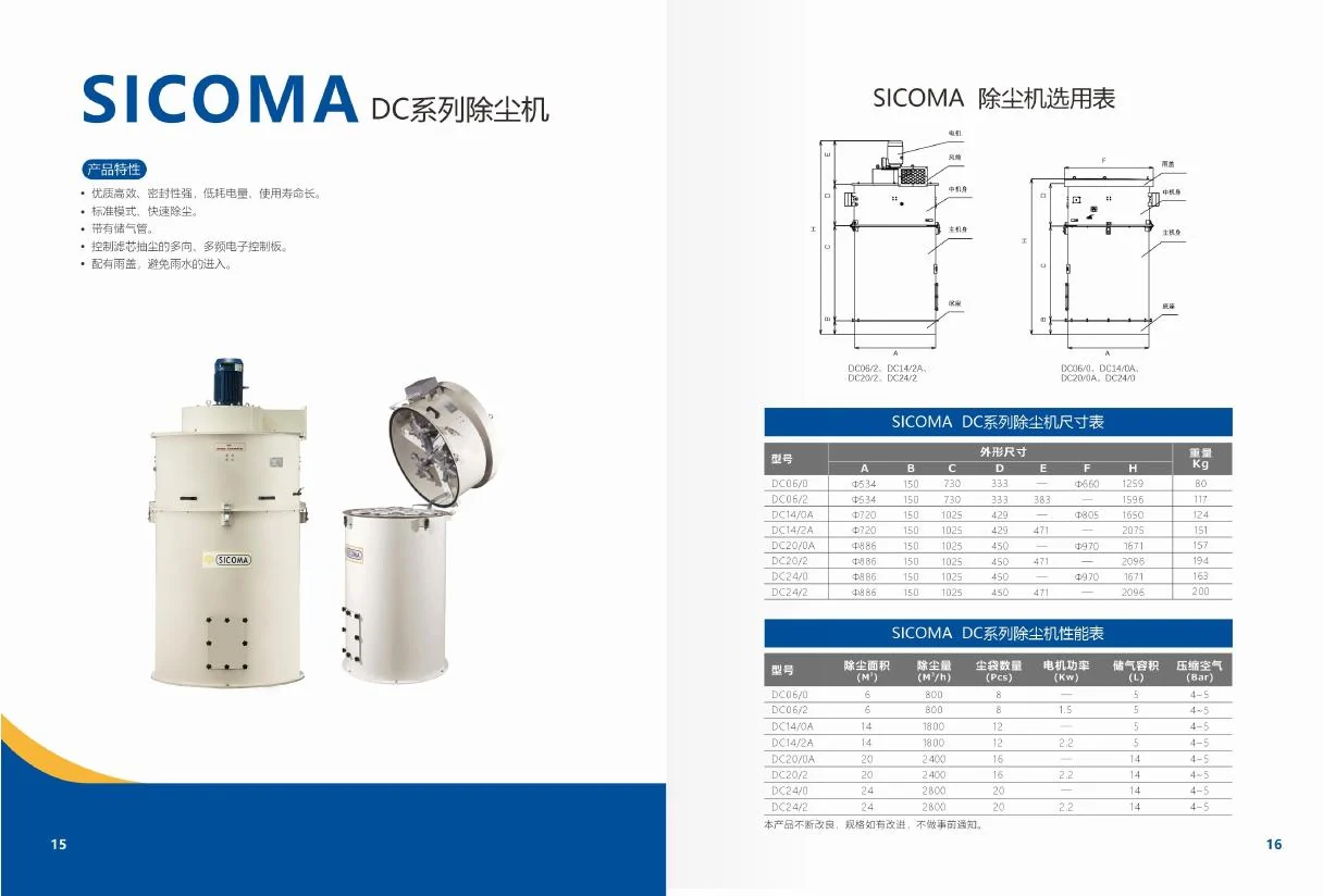
Silo dust collector sizing begins with the maximum credible air entering the silo during pneumatic filling. The collector must pass that air at an acceptable pressure drop while retaining dust and remaining cleanable. Silo volume alone is not a sizing airflow, and filter area alone does not prove that the complete system is safe.
The DC series silo dust collector provides published filtration-area and airflow data for model comparison. Match those values to the delivery method, dust properties, cleaning supply and protective devices before selecting a unit.
Define the air entering the silo
During tanker unloading, cement and conveying air enter together. Solids remain in the silo, while most of the air needs a controlled exit. The United States EPA has described dust collectors on pneumatically loaded cement silos as part of the airflow path that allows the silo to fill while limiting product loss in the exhaust. See the EPA’s ready-mix cement silo determination.
Ask the tanker or pneumatic-system supplier for the maximum conveying-air flow at the silo, not only the compressor’s nameplate displacement. Include the delivery pressure, pipeline length and diameter, vertical lift, expected unloading rate, purge sequence and end-of-delivery blowdown. Define whether two fill lines could operate together.
Do not use tonnes per hour as a direct substitute for air volume. Two systems can move the same mass with different air flows and pressure behavior.
Convert airflow into a filter-area check
A first-pass relationship is:
required effective filter area = design airflow ÷ permitted filtration velocity
The permitted filtration velocity, often called air-to-cloth ratio, must come from the filter supplier for the actual material, media, cleaning system and operating conditions. Do not copy a value from an unrelated dust. Fine cement, fly ash, moisture, oil carryover and compressed-air quality can change dust-cake behavior and cleaning performance.
| Input | What to document | Why it matters |
|---|---|---|
| Maximum inlet air | Normal fill, simultaneous fill and blowdown cases | Establishes vent demand |
| Dust | Material, fineness, moisture and temperature | Affects cake and media behavior |
| Filter media | Material, finish and limits | Sets compatibility and temperature boundary |
| Cleaning | Pulse pressure, air quality and sequence | Restores usable area |
| Pressure drop | Clean and normal operating range | Links airflow to silo pressure |
| Environment | Rain, condensation, ambient temperature | Affects blinding and corrosion |
The EPA’s fabric-filter overview explains that collected dust cake contributes to fine-particle capture and that pressure drop rises as dust accumulates. Cleaning must control resistance without stripping the cake so aggressively that filtration suffers.
Keep normal venting separate from pressure relief
A silo vent filter is part of normal filling. It is not the independent pressure-relief function. A blocked filter, excessive air flow or poorly controlled tanker blowdown can raise silo pressure even when the collector is correctly installed.
The UK government’s cement-handling process guidance states that inadequate filter airflow capacity can increase silo pressure. It also calls for automatic protection against overfill and overpressure and discusses maintaining the pressure-relief valve as a separate device.
Review the RV silo pressure relief valve as a separate product selection. The relief device, high-level protection, fill-line controls and dust collector need a coordinated cause-and-effect design. A product-page link does not establish a project pressure setting or certified relief capacity.
Specify pressure-drop evidence
Pressure drop across the filter is a useful operating indicator when measured with clear taps and a maintained instrument. A rising value can indicate accumulated dust, weak cleaning, moisture blinding or excessive airflow. An unexpectedly low value can indicate damaged media, leakage, an open bypass or an instrument problem.
The EPA lists particulate concentration or bag-leak detection, opacity, differential pressure, gas flow, cleaning operation and fan current among useful indicators. The correct set depends on the collector and permit. For a passive silo-top vent without an exhaust fan, the monitoring arrangement will differ from a central extraction baghouse.
Do not copy generic alarm numbers. Establish clean and loaded baselines during commissioning, then use the manufacturer limits and site requirements. Place the pressure taps where they measure the collector rather than an arbitrary section of pipe, and provide a method to detect plugged taps.
Check the cleaning system as part of sizing
Published filter area assumes that the cleaning system keeps enough area available. Confirm pulse pressure at the collector during operation, receiver volume, valve sequence, pulse duration and compressed-air quality. Wet or oily air can cause cement dust to adhere to the media.
Define when cleaning occurs. If cleaning continues during filling, verify that the pulse action and displaced air do not create an unacceptable pressure transient. If cleaning occurs only between deliveries, confirm that the collector can complete the next unloading cycle without exceeding its permitted resistance.
Collected dust must return freely to the silo or hopper. Inspect the path below the elements for buildup. A filter can pulse normally while discharged dust accumulates beneath it and removes effective area.
Coordinate the collector with filling controls
The delivery sequence should prove that the vent path and protective devices are available before material flow begins. A project cause-and-effect can include:
- Confirm the correct silo and fill connection.
- Prove the high-level and pressure instruments healthy.
- Confirm the dust collector and cleaning-air supply are available.
- Permit tanker discharge within the agreed pressure and flow limits.
- Stop or isolate delivery on high level, abnormal pressure or collector fault.
- Control final blowdown and record the delivery end state.
The cement screw conveyor venting guide explains displaced-air behavior at connected transfer points. That internal guide can help map the wider air path, but the silo collector must still be sized for its own maximum filling case.
Address dust exposure without making a compliance claim
Visible dust around a silo top, access hatch or fill coupling is evidence of a containment problem. It is not a complete exposure assessment. Where materials contain respirable crystalline silica, OSHA 29 CFR 1910.1053 requires employers within its scope to assess and control employee exposure. Applicable limits and duties depend on jurisdiction and material.
Collector selection should therefore define closed transfer interfaces, inspection access, safe filter change, dust handling and the method used to verify emissions or exposure. Do not claim that a filtration-efficiency percentage alone proves workplace compliance.
For combustible or uncertain powders, use a project-specific hazard assessment. The screw-conveyor explosion-risk guide explains why dust control and explosion protection are different questions. Equipment configuration must follow the identified material hazard and local rules.
Commission under a real delivery
Test with the expected tanker, fill line and material. Record start and finish time, material mass, conveying pressure, collector differential pressure, silo pressure, cleaning operation, visible emissions and alarms. Include the final purge or blowdown because that can create a demanding air condition.
Repeat enough deliveries to establish a clean-to-loaded pressure pattern. Inspect for leakage at the collector flange, access covers, fill connection and silo roof. Confirm that collected dust returns as intended and that instruments recover after cleaning.
If the silo pressure rises, do not simply increase a relief setting or silence an alarm. Check incoming airflow, filter resistance, cleaning, blocked dust return, instrument condition and the delivery procedure. Changes to tanker or pipeline operation can invalidate an earlier collector selection.
Conclusion
Silo dust collector sizing should connect maximum filling airflow to effective filter area, permitted filtration velocity, pressure drop and cleaning performance. Keep the vent filter separate from high-level and overpressure protection. A useful quotation includes delivery-air data, material properties, environmental conditions, monitoring points and a real-delivery acceptance test.