
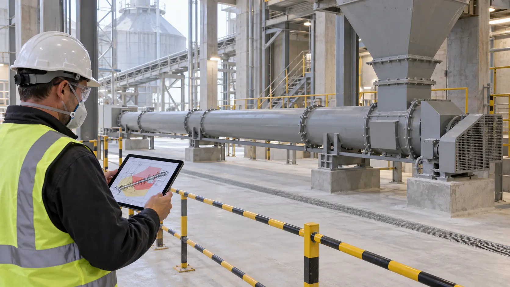
A cement screw conveyor explosion risk assessment should start by proving what the actual powder can do, then map where it may be released, dispersed, confined, and ignited. Do not assume that every cementitious powder is combustible, and do not assume that every material called cement is non-combustible. Composition, supplementary materials, organic additives, residual carbon, cross-contamination, particle size, moisture, and process history can change the answer.
For project-specific tubular cement conveying equipment, the material, interfaces, seals, drive, instruments, and protection scope must be defined in the approved project. VOGO’s public product information does not claim an explosion-pressure rating, hazardous-area certification, venting, suppression, or explosion-isolation function. Those requirements must come from the site’s documented risk assessment and applicable jurisdiction.
Start the cement screw conveyor explosion risk assessment with material evidence
A safety data sheet and supplier statement are useful starting points, but a trade name is not a test result for the powder that reaches the conveyor. Record every normal and credible off-spec constituent: cement type, fly ash or other supplementary cementitious material, pigment, grinding aid, organic additive, recycled dust, fuel residue, cleaning material, and possible cross-contamination. Define the finest fraction and lowest moisture condition reasonably expected, because collected fines may not match a bulk delivery sample.
ISO/IEC 80079-20-2:2016 provides test methods for identifying combustible dust and combustible dust layers so areas can be classified and electrical and mechanical equipment selected and installed correctly. Use a competent laboratory and representative samples when existing data do not cover the actual blend and operating envelope. The test plan should be chosen by the responsible fire-and-explosion specialist; depending on the decision being made, it may need screening plus properties used for ignition, consequence, venting, suppression, or isolation design.
Do not copy a published value from a vaguely similar powder into the project file. Link each result to the sample identity, preparation, method, laboratory, date, and covered range. If evidence supports a non-combustible conclusion for the actual material, document the conclusion and its limits rather than buying explosion equipment by habit. Other hazards—including respirable dust exposure, hot work, pressure, and a combustible contaminant—still need separate controls.
Map release sources, dust clouds, layers, and connected volumes
An explosion needs a combustible material dispersed at a hazardous concentration, an oxidizing atmosphere, an ignition source, and sufficient confinement for damaging pressure. The assessment should therefore follow the whole material path rather than treating the screw body as an isolated machine.
Mark the silo outlet, inlet transition, casing joints, inspection covers, shaft seals, discharge chute, flexible connector, filter connection, cleanout point, and every connected vessel or conveyor. Describe normal operation, filling, emptying, startup, shutdown, blocked discharge, seal failure, filter fault, cleaning, and maintenance. The cement screw conveyor venting guide covers process-air displacement and dust capture; explosion protection is a different design question and cannot be derived from extraction airflow alone.
IEC 60079-10-2:2026 addresses classification of areas where explosive dust atmospheres and combustible dust layers may be present. It treats dust clouds and layers separately because a settled layer can both create a fire hazard and become a source for a later cloud. Record housekeeping frequency and the surfaces that are difficult to inspect; writing “good housekeeping” without an observable standard or inspection route is not a control.
Under the European workplace framework, Directive 1999/92/EC requires assessment of explosion risk, classification of places where explosive atmospheres may occur, and an explosion-protection document. The EU-OSHA implementation guide helps apply that framework. Other jurisdictions use different legal structures, but the engineering record still needs a material basis, release assessment, ignition review, equipment selection, and protection concept.
Identify credible ignition sources at the conveyor
Use the actual installation and maintenance history, not a generic checklist alone. Credible sources around a cement screw include:
- an overheated drive-end, tail-end, or hanger bearing;
- flight-to-casing contact from buildup, misalignment, deflection, thermal growth, or a displaced component;
- an overloaded motor or reducer, failed brake, or unsuitable electrical device;
- static discharge from powder flow, non-conductive connectors, isolated metalwork, or ineffective bonding;
- hot work, smoking, portable tools, lamps, or temporary electrical equipment;
- tramp metal, foreign objects, or hot material entering from upstream;
- smouldering deposits or a fire propagating from connected equipment.
The bearing-temperature monitoring method explains how to establish comparable thermal baselines without inventing a universal alarm temperature. The coupling-guard design guide addresses access to rotating drive hazards. Neither condition monitoring nor guarding is an explosion-protection system by itself; each is one layer within the assessed risk-reduction plan.
For electrical and non-electrical equipment, use the site classification and applicable conformity framework to specify category, protection concept, temperature limits, ingress conditions, installation, inspection, and documentation. Do not place a certification mark or temperature class into a purchase order until the material data and area classification support it.
Do not treat the casing or screw as explosion isolation
An enclosed conveyor can reduce routine dust release, but enclosed does not mean airtight, explosion-pressure-resistant, or able to withstand a deflagration. Ordinary covers, seals, flexible connectors, gaskets, and supports may fail under pressure. A pressure rating requires defined design pressure, temperature, loads, materials, joints, inspection, and verification.
Likewise, a screw flight is not automatically an explosion-isolation device. Flame and pressure can propagate through inlet and discharge connections or into a dust collector, silo, hopper, or downstream machine. An ordinary slide gate, rotary valve, or non-return flap should not be credited as explosion isolation unless the complete device and installation are selected and validated for that duty.
Explosion venting, suppression, containment, and isolation solve different parts of the problem. Venting also needs a safe discharge location and a design that accounts for the protected enclosure and connected ducting. Suppression requires detection, agent delivery, controls, inspection, and response suited to the application. Select the concept through a qualified specialist using test data and applicable standards; do not attach a generic vent area or suppression bottle to a conveyor quotation.
Treat a silo outlet as feeder duty and one connected hazard boundary
A screw continuously covered by material below a hopper, bin, or silo is a screw feeder, not a control-fed conveyor. The explosion-risk review must include the silo and feeder as connected volumes, while the mechanical design must also address head load, increasing or variable pitch, tapered outside diameter or a justified mass-flow withdrawal arrangement, loaded-start torque, VFD low-speed torque, reducer service factor, and stall protection. A reduced-pitch inlet alone is not a complete withdrawal design.
The screw cannot independently prevent arching, rat-holing, or bridging. Outlet geometry, flow regime, moisture, consolidation, aeration or other flow aids, isolation valve, and feeder inlet must be reviewed together. Do not apply a normal control-fed conveyor capacity table to the flood-loaded section, and do not assume that closing a process gate provides verified explosion isolation.
Build a decision record before requesting quotations
Use a decision table that separates verified facts from engineering actions:
| Decision | Evidence required | Hold point before release |
|---|---|---|
| Is the actual powder combustible? | Current composition, supplier data, representative laboratory results where needed | Sample and covered operating range approved |
| Where can clouds or layers occur? | Release-source inventory, layouts, ventilation states, housekeeping observations | Area-classification drawing issued by the responsible party |
| Which ignition sources are credible? | Equipment list, temperatures, speeds, materials, bonding, maintenance and upset cases | Ignition-control schedule linked to tags |
| Can an event propagate to another volume? | Connection geometry, operating states, gates, filters, chutes and adjacent equipment | Isolation philosophy and interfaces approved |
| What protects each enclosure? | Material test data, enclosure strength, vent path, suppression or containment design | Protection calculations and certificates accepted |
| How will the system remain effective? | Inspection, proof-test, bypass control, housekeeping and change-management plan | FAT/SAT and periodic verification criteria agreed |
Provide bidders with the material test package, process and instrumentation diagram, hazardous-area drawing, normal and upset pressure, temperature, flow and speed cases, inlet duty, connected volumes, electrical supply, environmental conditions, protection philosophy, interface responsibilities, inspection access, and acceptance documents. Leave no ambiguity over who supplies detectors, isolation devices, controls, interlocks, relief paths, labels, certificates, or commissioning tests.
The UK’s DSEAR guidance follows the same practical sequence: identify dangerous substances and risks, eliminate or control them, reduce incident consequences, prepare emergency arrangements, train people, and classify areas where explosive atmospheres may occur. Translate that sequence into tagged project documents rather than a single unchecked “ATEX required” box.
Verify the installed system and control changes
Before handover, compare the installed machine with the approved drawings. Check equipment markings against the area-classification and equipment schedules, verify bonding and earthing continuity by the specified method, inspect seals and flexible connections, confirm housekeeping access, and witness protection and isolation tests under the approved safe procedure. Record device tags, test instruments, settings, results, defects, concessions, and responsible sign-off.
Commission normal and upset sequences without creating a hazardous dust cloud. Confirm what happens after loss of power, extraction, instrument air, a speed signal, or a protection-system fault. An emergency stop does not replace explosion isolation, and lockout/tagout remains necessary before opening the conveyor or entering a hazardous area for service.
Repeat the assessment after a material or supplier change, addition of fly ash or an organic additive, new recycle stream, throughput increase, speed change, filter modification, seal change, relocation, or protection-system alteration. Management of change must ask whether the original sample, area classification, ignition controls, and protection calculations still cover the installation.
Conclusion
A cement screw conveyor explosion risk assessment is defensible when it connects representative material evidence to release sources, dust layers, area classification, ignition controls, protection, isolation, and witnessed acceptance. Do not classify the hazard from the word cement, credit an ordinary casing or screw as containment or isolation, or purchase protection from borrowed dust data. Treat a flood-loaded silo outlet as screw-feeder duty and review the connected process as one hazard boundary.
Send VOGO the material test package, classified-area drawing, protection philosophy, interface schedule, and acceptance plan with the conveyor enquiry.
References
IEC 60079-10-2:2026 Explosive Atmospheres — Classification of Areas — Combustible Dust Atmospheres ↗ISO/IEC 80079-20-2:2016 Material Characteristics — Combustible Dusts Test Methods ↗Directive 1999/92/EC on Explosive Atmospheres at Work ↗EU-OSHA Guide to Implementing Directive 1999/92/EC ↗HSE Dangerous Substances and Explosive Atmospheres Regulations ↗