
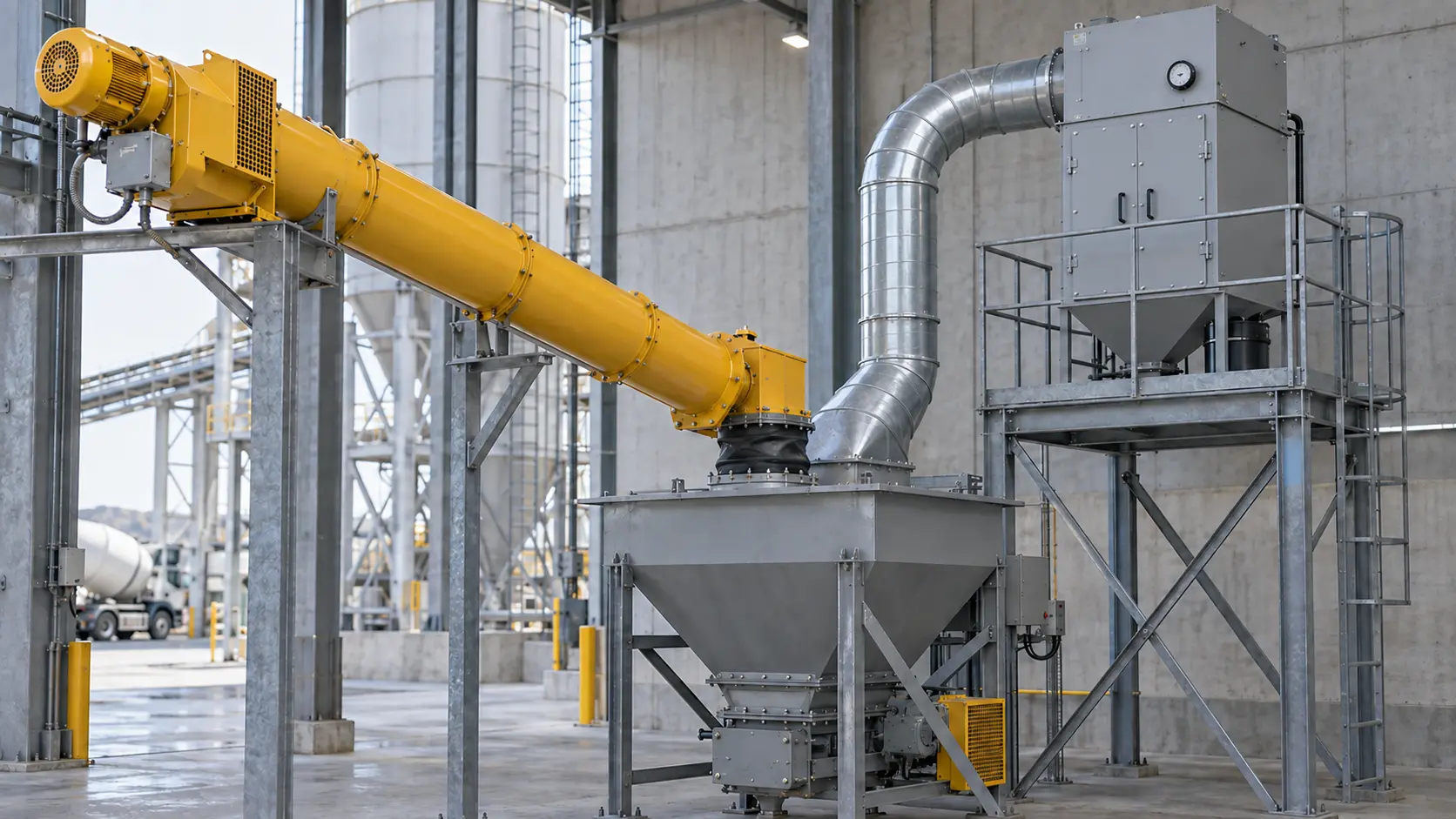
Cement screw conveyor venting should capture the air and dust released at the transfer point without turning the conveyor into an uncontrolled air duct. Start by enclosing the receiving connection, give displaced and entrained air a deliberate path to a dust collector or suitable process vent, and verify a slight inward airflow at leakage-prone openings. Cement capacity alone cannot determine extraction airflow.
The VOGO tubular cement conveyor range can be configured around stated material, layout, inlet, discharge, and interface requirements. Its published data does not assign a universal vent size, collector airflow, leakage class, or pressure rating. Those values belong to the installed conveying and dust-control system.
The US EPA concrete-batching emission guidance identifies cement transfer to weigh hoppers by screw conveyor as a particulate-emission source and lists enclosures, hoods, shrouds, and central duct collection among control methods. That system view matters: the dust plume normally develops where cement changes direction, falls, or displaces air—not simply because a screw rotates.
Cement screw conveyor venting starts at the air boundary
Draw a boundary around each transfer before selecting a duct. Mark where solids enter and leave, where air can enter, where air is deliberately extracted, and which connected equipment changes pressure. Include flexible sleeves, inspection covers, shaft seals, slide gates, weigh hoppers, filters, pneumatic filling lines, and downstream equipment.
Then classify the duty:
| Installation condition | Material-flow function | Venting implication |
|---|---|---|
| Upstream valve or separate feeder controls the flow into the screw | Control-fed screw conveyor | Analyze air carried with material plus displacement at the discharge enclosure |
| Screw inlet remains open below a hopper, bin, or silo | Flood-loaded screw feeder | Analyze the same air paths, but also design withdrawal geometry and loaded-start duty as a feeder |
| Conveyor discharges into a closed weigh hopper | Enclosed batch transfer | Provide replacement-air and extraction paths for the receiving volume and cutoff transient |
| Conveyor discharges into equipment under positive or negative pressure | Coupled pressure system | Define allowable pressure, isolation, backflow prevention, and collector compatibility for both machines |
A screw directly below a continuously open silo outlet is a feeder even if the plant calls it a conveyor. Its inlet may need increasing or variable pitch, tapered outside diameter, or a mass-flow withdrawal design. It must also be checked for head load, loaded starting torque, VFD low-speed torque, reducer service factor, and stall protection. Do not apply a control-fed conveyor capacity table to that flood-loaded section.
Venting does not cure arching, rat-holing, or bridging in the vessel. Those problems depend on outlet and hopper geometry, wall friction, moisture, consolidation, compaction, and the chosen flow aid or feeder withdrawal pattern.
Separate bulk displacement from extraction airflow
A useful first calculation converts cement mass flow to settled bulk volume:
Bulk volume rate = mass flow rate ÷ assumed bulk density
Suppose a proposed conveyor transfers 30 t/h and the project team uses 1.2 t/m³ as an explicitly stated preliminary bulk-density assumption. The bulk volume rate is:
30 t/h ÷ 1.2 t/m³ = 25 m³/h
That 25 m³/h is a screening estimate of the solid volume entering the receiver. It is not a collector selection and it is not a VOGO capacity claim. Cement can carry entrained air; falling material can induce additional air movement; a pneumatic source may pressurize the upstream vessel; and doors, sleeves, covers, and process connections admit leakage air. Several sources may also operate together.
HSE’s local exhaust ventilation guide explains that greater enclosure generally reduces the airflow needed for control, while turbulence and eddies can defeat capture. It also advises that an enclosure needs planned replacement air and that extraction flow must exceed the maximum volume flow created by the source. Those principles rule out multiplying the 25 m³/h screening number by an arbitrary factor and calling the result finished.
For an engineered airflow schedule, document at least:
- maximum and minimum cement rate, tested bulk density, drop height, and transfer geometry;
- air introduced by aeration, pneumatic filling, fluidization, purges, or connected machines;
- opening areas and the inward air velocity needed at unavoidable gaps;
- duct lengths, diameters, fittings, pickup entry loss, and expected dust loading;
- clean and loaded filter resistance, cleaning-air effects, fan curve, and damper positions;
- simultaneous operating cases and the pressure allowed by the conveyor, receiver, sleeves, and filters;
- safe discharge or return-air arrangement and the applicable exposure-control requirements.
Use measured airflow, pressure, or equipment-vendor data wherever possible. If source air volume or pressure pulses cannot be established, the correct result is an unresolved design input—not an invented vent diameter.
Put extraction where the dust is generated
At a typical screw-to-weigh-hopper transfer, the pickup belongs on the receiving enclosure with enough separation from the falling material to avoid unnecessary product carryover. The enclosure should guide replacement air inward and toward the pickup without a high-speed cross-draft that deflects the cement stream. A baffle or enlarged settling space may be considered, but its geometry and cleanability must suit the process.
Do not assume that connecting a strong suction duct to the upstream end of a long screw will control a discharge plume. Air may enter through shaft seals and cover joints, travel along the casing, entrain cement, and increase wear or collector load. Excess negative pressure can also collapse an unrated flexible sleeve or disturb weighing. The pressure target must therefore be modest, measurable, and compatible with every connected component.
Similarly, “enclosed” describes a physical casing; it does not mean airtight, dust-free, or pressure-rated. Leakage performance depends on flange flatness, gaskets, fasteners, shaft runout, seal type, wear, and operating pressure. The cement screw conveyor shaft-seal guide explains how pressure direction, purge, and runout affect the rotating interface. The screw conveyor sealing solutions article compares other leakage paths and maintenance approaches. Neither seal selection nor extra gasket material replaces a designed air path.
Define controls and acceptance evidence
A collector “running” signal proves only that a command or device state exists. The conveying permissive should use evidence appropriate to the risk and process, which may include fan status, damper position, duct static pressure, airflow indication, filter differential pressure, and receiver high-pressure alarm. Setpoints need installed-system commissioning data; do not copy another plant’s values without checking the fan, duct, filter, and instruments.
HSG258 recommends simple airflow or pressure indicators so operators can see whether extraction is performing. Differential pressure across a filter is especially useful when the clean and normally loaded ranges are recorded. A high reading may indicate loaded media, failed cleaning, a closed damper, or a restricted duct. A low reading can indicate a stopped fan, open access door, broken filter, disconnected duct, or instrument fault. Neither direction diagnoses the fault by itself.
| Symptom | Check first | Do not assume |
|---|---|---|
| Dust puff at conveyor discharge on startup | Start sequence, receiver vent path, damper position, fan proof, residual material | A larger shaft seal will absorb a pressure pulse |
| Dust at several cover joints | Actual casing pressure, blocked vent, filter differential pressure, fastener and gasket condition | An enclosed casing is airtight |
| High collector differential pressure | Cleaning cycle, hopper discharge, media loading, instrument zero, fan operating point | Higher suction is always available |
| Excess cement in collector | Pickup location, entry velocity, drop trajectory, baffles, fan/damper setting | More airflow always improves control |
| Hopper weight unstable during filling | Flexible-connection forces, extraction pressure variation, filter cleaning pulses | The weighing error is only a load-cell problem |
The eCFR’s respirable crystalline silica rule requires specified employers to use feasible engineering and work-practice controls and addresses exposure assessment and housekeeping. Applicable legal duties depend on jurisdiction and exposure conditions, but dust seen escaping a transfer should be treated as a control failure to investigate, not merely a cleanup issue. Do not use dry sweeping or compressed air as a routine substitute for source control where those methods can create airborne dust.
Commission the complete transfer system
Run acceptance tests under safe, representative conditions rather than judging the empty machine alone. Record the material, rate, upstream and downstream equipment states, fan and damper settings, clean or loaded filter condition, ambient drafts, and instrumentation calibration.
The commissioning sheet should include:
- Confirm approved drawings, pressure limits, collector duty, relief arrangements, guarding, and isolation points.
- Inspect duct supports, flexible sleeves, access covers, gaskets, shaft seals, filter media, rotary valves, and dust-hopper discharge.
- Prove the fan, damper, pressure or airflow indication, filter differential-pressure alarm, and conveying permissive.
- Observe airflow direction at intended openings using a safe visualization method; keep people clear of moving equipment and dust exposure.
- Test minimum, normal, and maximum intended cement rates plus credible simultaneous-source cases.
- Watch the startup, steady transfer, cutoff, filter-cleaning, and shutdown transients for visible release or abnormal pressure.
- Record duct static pressure, filter differential pressure, fan state, material rate, and observations at repeatable test points.
- Stop and isolate the equipment before opening, clearing, or adjusting it. HSE’s machinery safety guidance emphasizes isolation for blockage removal, cleaning, and adjustment.
Acceptance should state measurable conditions: tested operating cases, allowable visible release or workplace exposure criterion, pressure range, alarm response, and instrument locations. “No dust” without a test method and operating condition is not an auditable specification.
Conclusion
Cement screw conveyor venting is a transfer-system design task, not a duct-size shortcut. Use cement throughput and bulk density only to screen solid displacement; determine extraction from the real air sources, enclosure openings, duct and filter losses, simultaneous operation, and permitted equipment pressure. Locate the pickup at the dust-generating enclosure, provide controlled replacement air, and commission the system with pressure, airflow, filter, and visible-release evidence. Above all, never treat an enclosed conveyor as automatically airtight or pressure-rated.
For a project review, send VOGO the material data, layout, transfer rates, pressure sources, receiver details, dust-control basis, and required acceptance tests.