
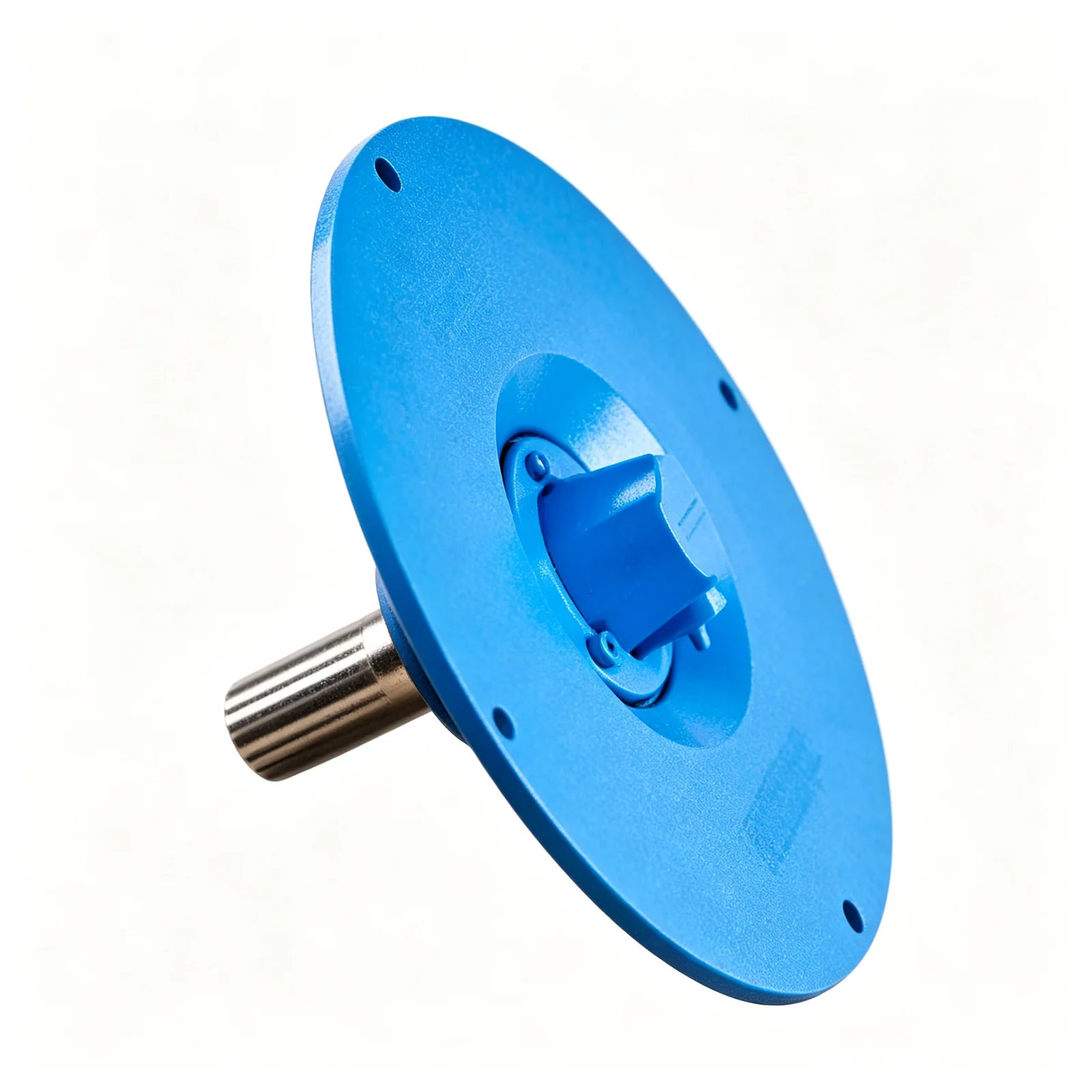
A cement screw conveyor shaft seal cannot be selected from the word “enclosed.” Enclosed construction limits exposure, but it is not automatically airtight, dust-free or pressure rated. Define the leakage target, pressure direction, shaft speed and runout, temperature, abrasion, purge supply, access and bearing arrangement.
VOGO’s tubular cement screw conveyor configurations limit external exposure through a rigid casing. The quotation must still define seals, flanges and operating conditions.
Translate “No Dust” Into a Specification
Ask these questions:
- Is casing pressure normally positive, negative or near atmospheric?
- What are normal and upset pressure ranges?
- Is visible dust prohibited, or is a measured leakage/test class required?
- Is air ingress also limited?
- What shaft speed, diameter, runout and temperature apply?
- Is clean purge gas available and monitored?
- Can packing be adjusted while remaining outside guarded motion?
- How is leaked material kept away from the bearing?
Without answers, “dust-tight” is not an acceptance test.
Cement Screw Conveyor Shaft Seal Decision Matrix
The KWS seal guide describes plate, waste-pack, split-gland, flanged-gland and other arrangements. Selection is application specific.
| Arrangement | Useful feature | Main limitation to resolve |
|---|---|---|
| Plate/lip | Compact and economical | Shaft runout, lip wear and pressure capability |
| Waste pack | Simple renewable packing | Adjustment and housekeeping |
| Split gland | Packing can be serviced in sections | Correct compression and shaft condition |
| Flanged gland | Multiple adjustable packing rings | Friction, heat and maintenance |
| Air purge/mechanical | Higher containment potential | Clean supply, controls and failure mode |
Do not infer a pressure rating from the seal category. Housing, end plate, flanges, gaskets, cover, shaft and connected equipment must all share the stated rating.
Protect the Bearing
KWS trough-end guidance describes pedestal and bulkhead layouts that create separation for heavier seals and help keep leakage away from bearings or reducers. Fine cement entering a bearing can contaminate lubricant and accelerate wear.
SKF’s industrial seal guidance treats leakage control and contaminant exclusion as distinct functions influenced by speed, temperature and abrasive exposure. A dust lip or purge must be matched to the actual shaft and environment.
Diagnose Leakage Before Tightening
| Symptom | Possible cause | Check |
|---|---|---|
| Dust only at startup | Positive-pressure pulse | Venting and sequence |
| One-sided leakage | Runout or misalignment | Shaft and drive alignment |
| Hot packing | Excess compression or poor lubrication | Adjustment and surface speed |
| Repeated lip failure | Rough shaft or eccentric motion | Shaft finish and runout |
| Bearing contamination | Inadequate separation | Trough-end arrangement |
| Air ingress | Negative casing pressure | Seal direction and joint leakage |
Blindly tightening packing can increase friction, heat and shaft wear without correcting pressure pulses. The blockage guide helps identify restrictions that raise casing pressure. The maintenance checklist shows how to trend seal drag and leakage.
Acceptance and Maintenance
Specify visible-leak inspection, any quantitative test, purge pressure/flow, alarm response, allowable temperature, adjustment method and spare packing. Record baseline empty current because seal drag contributes to friction. Isolation is required before hands or tools enter the guarded shaft area.
KWS material-design guidance notes that very dusty materials require special sealing; that statement is not a guarantee for an unspecified standard seal.
Include Casing Pressure in the Process Design
Shaft seals cannot compensate for an uncontrolled pressure source. A receiving hopper with a blocked vent can pressurize the conveyor. Pneumatic silo filling can send pressure pulses through an open connection. A downstream dust collector can place the casing under negative pressure and pull ambient air inward.
Create a pressure schedule containing normal, startup, shutdown and upset values, plus duration and direction. Identify the device that limits each pressure. If the pressure is unknown, the seal supplier cannot confirm leakage or purge requirements.
The entire boundary includes inlet and discharge flanges, casing joints, inspection covers, gaskets and shaft penetrations. A high-performance shaft seal on a lightly gasketed casing does not create an airtight system.
Evaluate Purge Seals as an Instrumented Utility
A purge arrangement needs clean, dry and compatible gas at a pressure above the local casing pressure. Specify normal flow and pressure, filtration, dew point if relevant, regulator, check valve, low-pressure alarm and response to supply failure.
Too little purge may allow cement into the seal. Excess purge can aerate material, disturb weighing, raise downstream filter load or create leakage elsewhere. The supplier must define an operating window. Do not use plant air containing oil or moisture without confirming compatibility.
If the conveyor serves a potentially hazardous dust application, explosion and ignition risks require a separate competent assessment. A purge is not, by itself, an explosion-protection system.
Control Shaft Runout and Surface Condition
A seal lip or packing follows the shaft only within its design runout and misalignment limits. Bent screws, worn bearings or a moving drive can create cyclic gaps. Abrasive cement trapped at the interface can score a shaft sleeve and make repeated seal replacement ineffective.
Measure runout at the seal location, not only at the motor. Inspect shaft diameter, finish, hardness and wear groove. A replaceable sleeve may be appropriate where the approved design supports it. Confirm sleeve retention and concentricity.
Select With a Decision Matrix
| Duty | Likely priority | Questions before selection |
|---|---|---|
| Near-atmospheric transfer | Dust housekeeping | Is visible leakage criterion sufficient? |
| Slight negative pressure | Limit air ingress | What vacuum and process effect apply? |
| Intermittent positive pulse | Prevent dust escape | What peak, duration and vent path apply? |
| Hot cement | Material compatibility | What shaft and seal temperatures occur? |
| Abrasive service | Wear resistance | Is a sleeve or renewable packing provided? |
| Purged containment | Controlled barrier | What supply, alarm and failure response apply? |
The matrix narrows discussion; it does not rate a seal.
Seal Commissioning Test
With the conveyor empty, record shaft speed, seal temperature, adjustment, purge values and motor current. Under controlled cement load, observe the defined leakage points and casing pressure. Repeat at normal and upset conditions that can be tested safely.
After the first operating period, inspect packing settlement, lip track, fasteners and bearing cleanliness. Record every adjustment. If maintenance repeatedly tightens packing to control leakage, calculate the added drag and investigate runout or pressure instead of continuing indefinitely.
Seal Information Required in the Proposal
The proposal should state seal type, packing or lip material, shaft/sleeve specification, design runout, speed and temperature limits, pressure direction and range, purge utility, bearing separation, adjustment method, spare parts and acceptance criterion.
Avoid commercial wording such as “zero leakage” unless a test method, medium, pressure, duration and detection threshold are written. The same caution applies to “dust-tight,” “airtight” and “pressure rated.”
Lifecycle Cost Comparison
Compare seals on packing or cartridge cost, adjustment labor, purge-air consumption, sleeve wear, bearing contamination risk and downtime, not purchase price alone. An inexpensive seal requiring frequent adjustment can be unsuitable where access needs scaffolding or a silo shutdown.
State which parts are consumable and whether replacement requires removing the bearing or drive. Include those steps in the isolation and lifting plan.
Conclusion
Choose a cement screw conveyor shaft seal from a measurable containment target and real operating conditions. Define pressure direction, runout, speed, temperature, abrasion, purge and bearing separation. Treat enclosed, airtight and pressure rated as different claims. Put the seal arrangement and acceptance test on the approved drawing and proposal.