
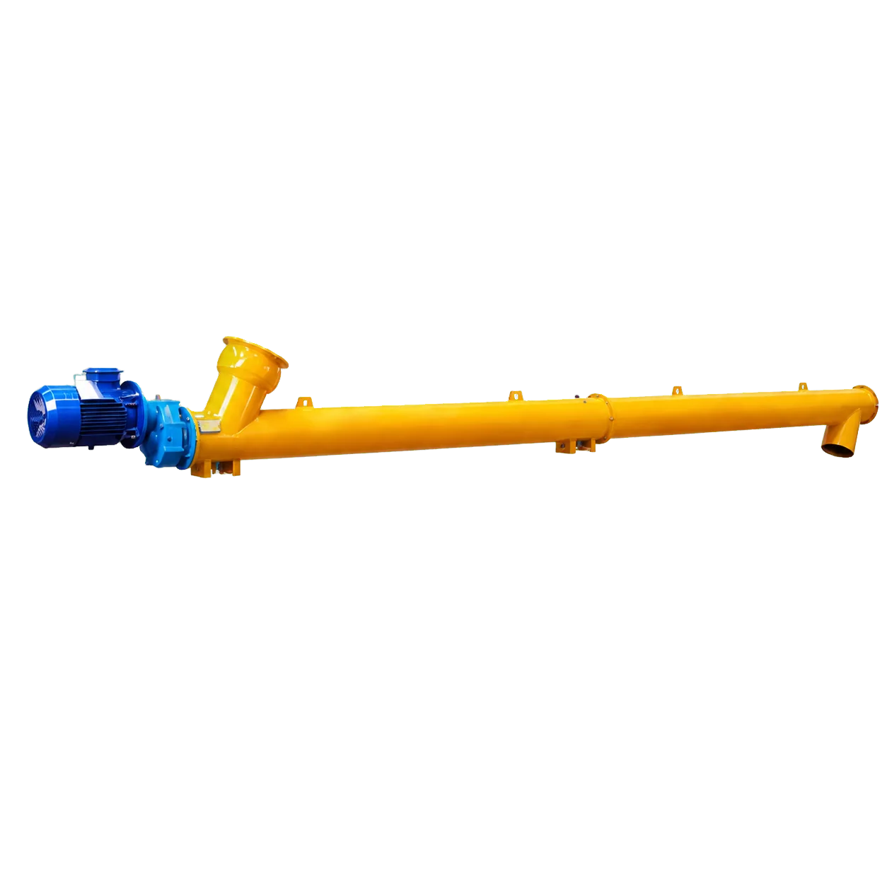
In bulk solids handling at cement and powder processing plants, the screw conveyor trough is often overlooked in favour of the internal flighting or drive components. The fabrication quality of the trough, whether U-shaped or a rigid tubular body, determines the operational integrity of the system. Poorly fabricated troughs cause dust leakage at flange joints and excessive vibration from misalignment. Internal weld spatter or irregular clearances can also lead to premature wear. Beyond mechanical inefficiencies, compromised trough integrity often results in environmental compliance failures and cross-contamination of sensitive products. Engineers and procurement managers must understand trough fabrication and welding quality control. A properly fabricated trough provides a sealed conveying path and precise internal clearances. It also forms a stable foundation for the rotating shaft and flights. This guide covers the manufacturing aspects of screw conveyor troughs, including welding techniques, machining tolerances, and quality control (QC) checkpoints. Setting clear expectations for Factory Acceptance Tests (FAT) ensures the delivered equipment meets the requirements for continuous, enclosed powder conveying.
Welding techniques and internal finish
The welding process used to fabricate the conveyor trough affects structural integrity and internal flow. Tubular screw conveyors use a compact conveying path to limit external dust exposure, so continuous welding is preferred over intermittent welding. Continuous welds, especially those made with Tungsten Inert Gas (TIG) or Metal Inert Gas (MIG) welding, provide a seal that prevents fine cementitious powders from escaping through microfissures. Intermittent welding is acceptable for non-critical structural supports or external stiffeners, but it creates gaps prone to dust leakage under the slight positive or negative pressures generated during conveying. For stainless steel troughs handling hygienic or highly corrosive powders, TIG welding with appropriate argon shielding gas is essential to prevent sugaring (oxidation) on the root pass.
The internal finish of the weld seams also matters. When handling abrasive materials like cement, fly ash, or dry-mix mortar, weld spatter, undercut, or a rough internal profile traps material. This buildup reduces the effective cross-sectional area of the trough and accelerates localized wear on the screw flights. In practical applications, such as conveying titanium dioxide or food-grade additives, even microscopic crevices can harbour bacteria or cause product discolouration. Standard fabrication requires internal weld seams to be ground smooth and, where necessary, pickled or polished to eliminate crevices. Following structural welding codes, such as AWS D1.1 for steel or EN ISO 15614 for European standards, provides the required penetration and strength without compromising the internal geometry of the trough. Proper weld profiling allows material to flow smoothly without stagnation, maintaining consistent batching accuracy in concrete production.
Machining tolerances: straightness and flange flatness
Dimensional accuracy of the trough during machining and forming is required for proper assembly and long-term reliability. The two main geometric tolerances are trough straightness and flange flatness, also called flange perpendicularity.
Trough straightness keeps the conveyor on a true centreline along its length. A bowed, twisted, or improperly rolled trough forces the internal screw shaft to bend. This puts high stress on the hanger and end bearings. The misalignment causes vibration, higher power consumption, and faster wear on the flights and trough liner. To mitigate thermal distortion during the welding of long tubular sections, fabricators must employ balanced welding sequences or use precision rolling jigs. Industry standards such as JB/T 15279-2024 for tubular screw conveyors specify limits on the straightness of the shell and spiral body, typically restricting deviation to no more than 1 mm per 3 metres of length, to maintain smooth operation and prevent mechanical binding.
Flange flatness and perpendicularity are also necessary. Screw conveyors are usually made in modular sections joined by flanged connections. If the flange faces are not flat and square to the trough axis, bolting the sections together causes structural stress and creates uneven gaps. These gaps compromise the gasket or seal and cause persistent dust leakage at the joints. This leakage can overwhelm local dust collection systems. During fabrication, flange faces must be machined or jigged and welded to maintain close tolerances. Keeping flange perpendicularity within specified limits allows each module to align with the next and creates a uniform sealing surface along the conveyor. In long-span installations, maintaining strict flange flatness ensures that intermediate support brackets do not induce unintended bending moments into the trough assembly.
Quality control checkpoints and FAT procedures
The quality control (QC) protocol must verify fabrication tolerances and welding standards before the equipment leaves the factory. The Factory Acceptance Test (FAT) allows the procurement team and QC inspectors to validate these parameters.
Inspectors check internal clearance and weld quality through inspection hatches. They use limit gauges or feeler gauges to verify the clearance between the screw flight and the trough wall. Standards require the minimum clearance to be at least 50% of the nominal design value to prevent contact during thermal expansion or shaft deflection. Inspectors also perform visual and tactile checks to confirm internal welds are smooth and free of spatter. For critical applications, non-destructive testing (NDT) methods, such as dye penetrant inspection, may be specified to verify the absence of surface-breaking defects in continuous welds.
Technicians measure geometric tolerances using a taut wire or laser alignment tool to check trough straightness along the exterior. They check internal shaft straightness with a dial indicator between centres. An equal height block and a precision square measure flange perpendicularity to ensure the gap stays within specified limits.
An unloaded run test follows. The conveyor operates for a specified duration to monitor bearing temperature rise and noise levels. Excessive noise or vibration during this test indicates trough misalignment or internal interference. Signed inspection reports record these checks for site installation and commissioning.
Material selection and surface protection
The choice of base material and subsequent surface treatments fundamentally dictate the trough’s lifespan and suitability for specific environments. Carbon steel (such as S235JR or S355JR) remains the standard for general cement and aggregate handling due to its high tensile strength and cost-effectiveness. However, when processing highly abrasive materials like silica sand or corrosive substances such as certain chemical fertilisers, the internal surface requires additional protection. Applying wear-resistant linings, such as chromium carbide overlay or polyurethane coatings, significantly extends the trough’s operational life by shielding the base metal from direct particle impact.
For environments requiring strict hygiene or handling moisture-sensitive powders, stainless steel grades like 304 or 316L are specified. While stainless steel offers superior corrosion resistance, it is more susceptible to galling and requires careful handling during fabrication. Furthermore, external surface protection is equally critical. In coastal or highly humid plant environments, external surfaces should be grit-blasted to Sa 2.5 standard and coated with a high-build epoxy or polyurethane paint system. This prevents external corrosion that could eventually compromise structural welds and flange connections, ensuring the conveyor maintains its pressure-bound integrity over decades of service.
Conclusion
The fabrication and welding quality of a screw conveyor trough directly affects the performance of a bulk solids handling system. Continuous welding, smooth internal finishes, and strict machining tolerances for straightness and flange flatness prevent dust leakage, vibration, and premature wear. Factory Acceptance Test checkpoints verify these parameters before dispatch to site. For enclosed powder conveying, specifying high fabrication standards is as important as selecting the correct capacity and diameter. Selecting the correct bulk material handling equipment determines operational efficiency and reliability. Evaluate the required capacity, screw diameter, and environmental conditions to optimise system performance. VOGO Machine’s cement screw conveyors meet these requirements with customised configurations for industrial applications, utilising project-specific configurations and rigid tubular bodies to maintain a compact conveying path and limit external dust exposure. Available diameters range from Ø89 mm to Ø407 mm. To review the selection parameters, download the datasheet, and explore technical specifications, visit the cement screw conveyor product page at https://vogomachine.com/cement-screw-conveyor/en/.