A silo pressure relief valve inspection must verify more than whether the lid looks closed. The inspection should confirm that the valve can move freely, is clean and undamaged, has a documented pressure setting, and has adequate relieving capacity for the maximum credible incoming airflow. It must also test the surrounding filter, pressure alarm and fill-shutoff system.
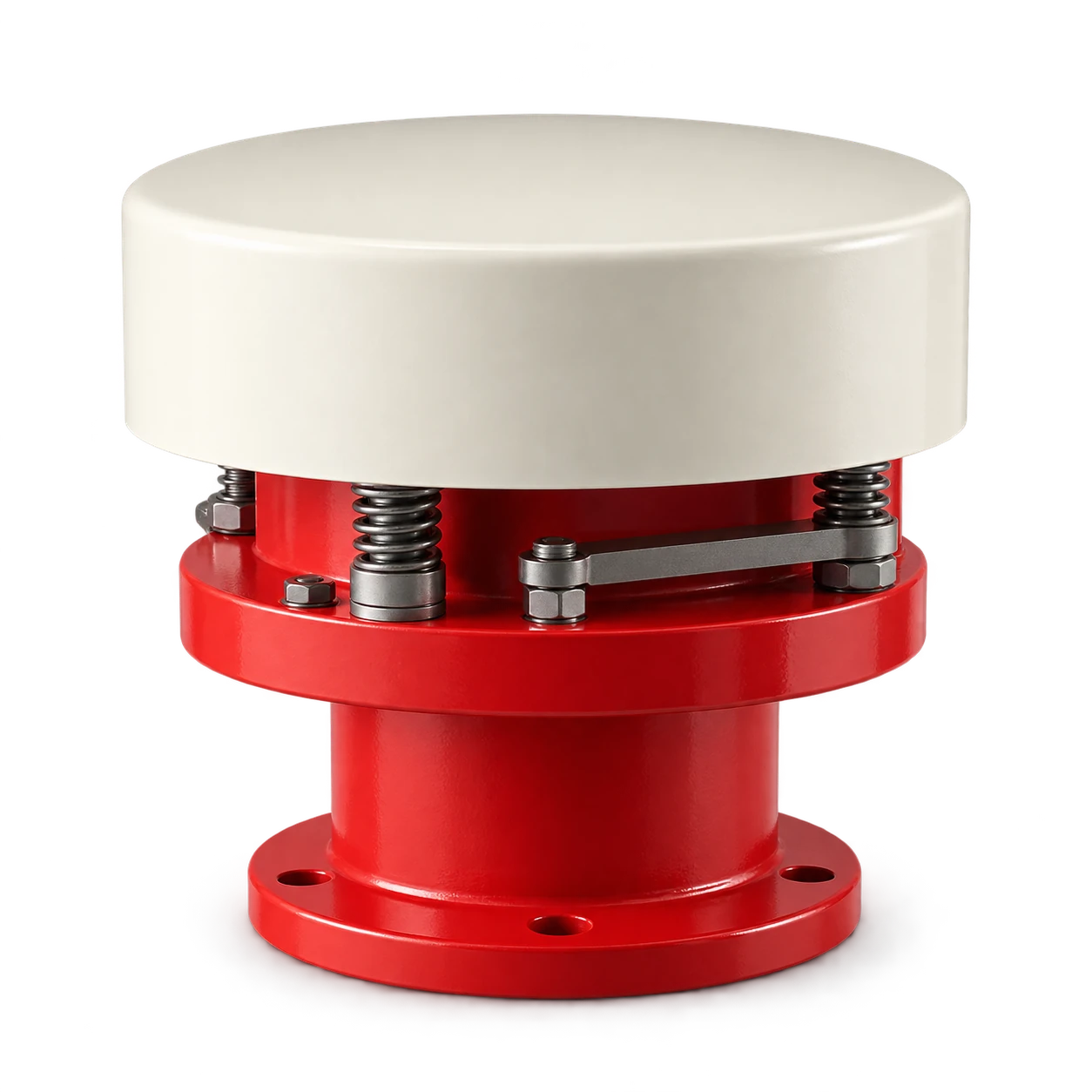
The RV silo pressure relief valve is cataloged for a Ø250 installation connection. The catalog does not publish a universal set pressure or flow capacity. Those values must come from the silo designer, the selected valve documentation and the actual pneumatic-filling duty.
Treat the relief valve as the last layer, not the control system
Bulk powder silos are commonly designed for low pressure, not as general-purpose pressure vessels. The Mineral Products Association’s silo over-pressurisation guide describes the pressure relief valve as a final safety device that opens at a preset pressure. The same guide emphasizes correct filter capacity, maintenance and control of the delivery air surge at the end of filling.
Define the protection layers and their owner:
| Layer | Normal purpose | What inspection must prove |
|---|---|---|
| Fill supervision and tanker control | Prevent avoidable overfill or excessive air input | Operator can stop delivery and secure the inlet |
| High-level device | Detect material near the safe fill limit | Alarm and filling permissive operate end to end |
| Vent filter | Pass displaced conveying air while retaining product | Media, cleaning system and discharge path are not blinded |
| Pressure indication/alarm | Detect abnormal pressure before or during relief | Sensor, set points, HMI and alarm response are functional |
| Pressure relief valve | Limit pressure when other controls are insufficient | Correct valve, setting, movement, discharge path and capacity |
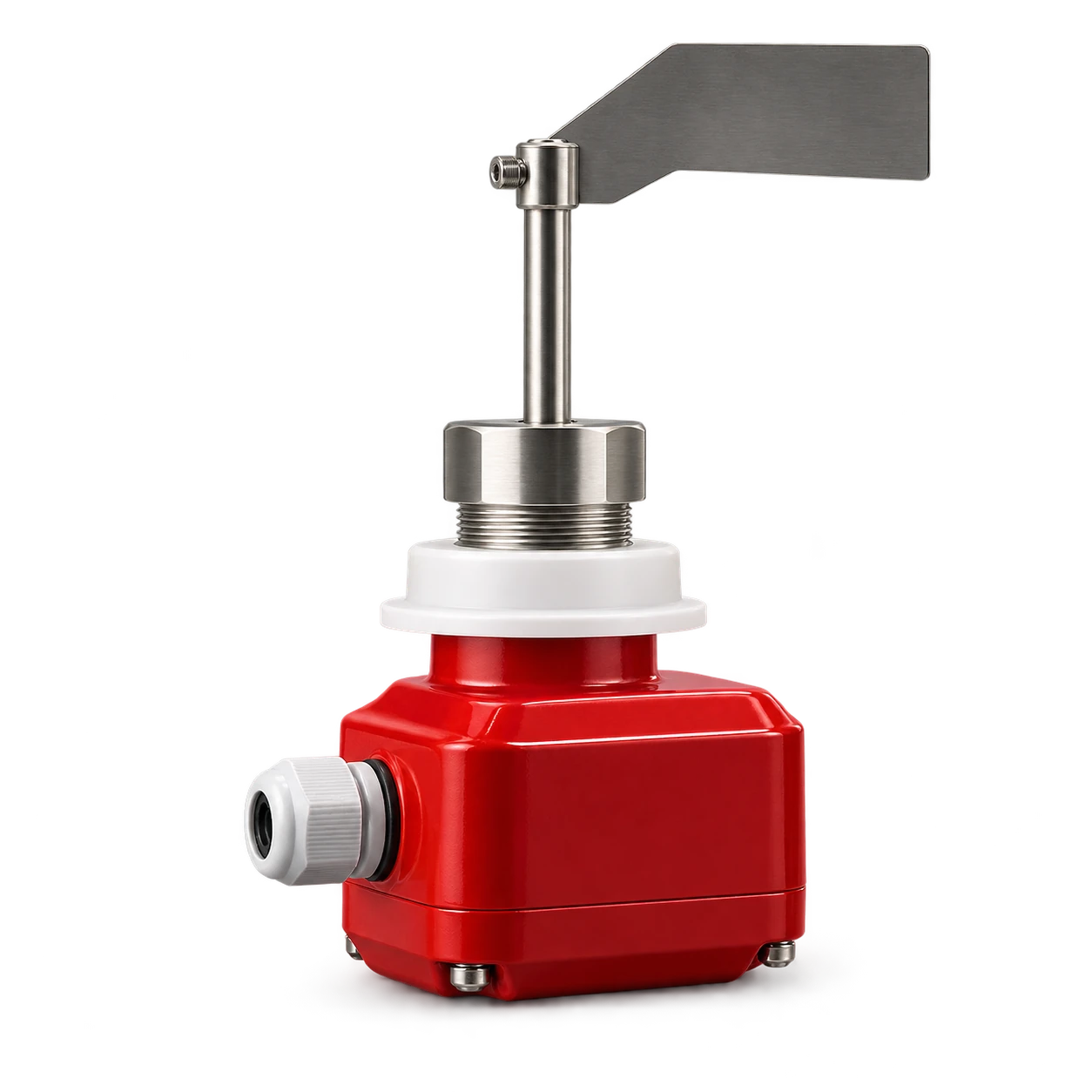
The rotary paddle level switch installation guide explains point-level proof testing. A high-level switch helps prevent overfill, but it neither vents conveying air nor replaces a relief valve.
Establish approved pressure and flow data first
Before touching the valve, obtain the silo design pressure, maximum allowable positive and negative pressure where applicable, approved valve set point, maximum credible inlet airflow and filter venting capacity. The UK Health and Safety Executive’s plant design-code guidance calls for the relief-device set pressure to be considered against the equipment design pressure and for relief to a controlled, safe location.
Do not copy a pressure value from another silo. Two vessels with the same diameter can have different roof strength, filter condition, fill-line arrangement and air-delivery envelope. Likewise, a matching flange does not prove that the valve has enough relieving capacity.
The required capacity review should cover at least:
- normal conveying air plus displaced vessel air;
- tanker blow-down or end-of-delivery surge;
- credible failure of aeration or fluidization air;
- restriction from filter contamination or failed cleaning;
- combined inlets if more than one air source can operate;
- the valve’s certified or supplier-documented flow at an approved pressure basis.
This is a system calculation for the responsible designer. Do not infer capacity from connection diameter alone, and do not describe an ordinary spring-loaded valve as explosion venting or pressure-vessel protection unless it has the relevant documented approval.
Perform a safe external inspection
Stop filling, close and secure the inlet, isolate automatic aeration and follow the site’s energy-control procedure before removing covers or placing hands near moving parts. OSHA’s hazardous-energy guidance notes that electrical, pneumatic, mechanical and stored energy can injure workers during service. Residual silo pressure and falling powder are part of that assessment.
From a safe access position, inspect and document:
- valve identity, connection size and direction against the equipment record;
- corrosion, impact damage, cracked housings, loose fasteners and distorted lids;
- product buildup, caking, hardened deposits or foreign material around moving parts;
- weather hood, discharge route and any screen for obstruction;
- gasket and seat condition without assuming a relief valve is an airtight isolation device;
- springs, weights, bellows or adjustment components only as exposed by the approved manual;
- signs of a recent lift, including powder staining around the outlet;
- access clearance for service and a discharge area that keeps people away.
A visual check cannot verify pressure calibration. Nor does free manual movement prove the valve will open at the correct differential pressure or pass the required flow.
Separate movement, set-point and capacity tests
Use three distinct test statements so that one weak check is not reported as full validation.
Movement check: after isolation and cleaning, exercise the mechanism only by the manufacturer’s permitted method. Record sticking, uneven travel, spring damage or a lid that does not reseat. Never add lubricant unless the manual specifies the product and location; incompatible lubricant can capture dust or attack seals.
Set-point test: a competent service provider applies a controlled pressure method or approved test rig and records the initial opening or lift behavior against the silo designer’s approved value. Seal or lock adjustments after calibration where specified. Site personnel should not “turn the spring until the alarm stops.”
Capacity verification: compare the selected valve’s documented relieving curve and conditions with the maximum credible air input and the silo pressure limit. A successful low-flow lift test does not demonstrate full-flow capacity.
Record the test equipment, calibration status, method, as-found result, as-left result, technician, date and next action. If the valve cannot be tied to approved design data, treat that as an engineering information gap rather than inventing a pass value.
Proof-test the whole filling protection function
The relief valve should not be made to lift during every routine functional test. Use approved simulations to test the earlier layers without pressurizing the silo beyond normal limits:
- simulate high level and confirm the filling alarm or permissive;
- simulate the pressure alarm and confirm the operator response;
- prove that the tanker connection can be isolated and locked;
- verify filter cleaning, differential indication where fitted and unobstructed exhaust;
- confirm alarm labels distinguish high level from high pressure;
- check event records and communication with the delivery driver;
- verify that reset does not permit an uncontrolled restart.
The MPA guide links blocked filters, seized or undersized relief valves and poor maintenance to silo over-pressure events. The silo dust collector sizing guide covers the filling-air and vent-filter duty in more detail. Neither filter sizing nor a new valve alone closes the protection case; the interfaces must be proven together.
Respond to any lift or pressure alarm as an incident
A 2026 SafeQuarry report, Faulty aeration valve causes silo over pressurisation, describes a failed-open aeration valve that blinded the filters during tanker discharge. Supervision stopped the delivery, and inspection found evidence that the pressure alarm and PRV had operated. The initiating fault was not the relief valve itself.
Use that system logic after any valve lift:
- Stop pneumatic filling and secure the inlet.
- Keep people clear of the relief discharge and roof area.
- Record pressure, alarms, delivery stage and visible discharge without approaching an unsafe vessel.
- Check level, filter condition, cleaning air, aeration valves, pressure sensing and fill controls.
- Have the relief valve inspected and, when required, recalibrated by a competent service provider.
- Correct the initiating fault and perform a controlled functional test before return to service.
Do not simply reset the alarm or increase the relief setting. Powder around the valve is evidence of an event or leakage path; cleaning it without recording the cause removes useful diagnostic evidence.
Silo pressure relief valve inspection record
Set the routine interval from the valve manual, silo designer, duty severity, environmental exposure and site risk assessment. Add an event-driven inspection after a lift, pressure alarm, filter failure, product change, long shutdown, roof work or any maintenance affecting filling air.
The service record should include:
- valve model, serial or asset number and product handled;
- approved set point and source document;
- design-pressure reference and capacity calculation reference;
- as-found cleanliness, movement and seal condition;
- calibrated test results where performed;
- filter and alarm proof-test results;
- defects, photographs, parts replaced and return-to-service authorization.
This record distinguishes a real inspection program from a tick-box visual check. It also prevents an undocumented replacement spring, weight or adjustment from changing the protective function.
Conclusion
Silo pressure relief valve inspection combines condition checks, approved set-point testing, capacity verification and proof of the complete filling-control system. Keep the valve clean and free, but do not declare it adequate until its setting and relieving curve match the silo’s design pressure and credible airflow. After any lift, stop filling and find the initiating fault before restart. For the RV valve, provide the silo connection, approved pressure data, air-flow case and environment for supplier review.