Bulk solids slide gate valve selection begins with duty and load condition, not nominal opening alone. Define whether the gate isolates or controls flow, whether it must close through moving or settled material, and whether the system is gravity-fed or pressurized. Then confirm material behavior, clear opening, leakage requirement, actuator thrust and stroke, interfaces, cycle rate, feedback and maintenance isolation with the supplier.
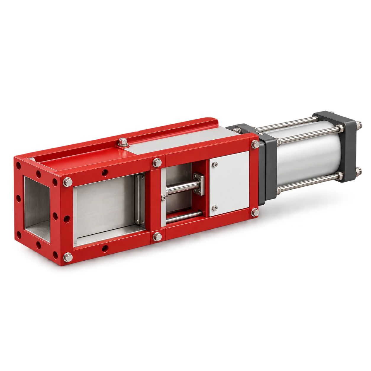
The SG Slide Gate Valve is a 200–800 mm catalog connection class for silo isolation and discharge control. VOGO’s published selection basis is opening size, actuator type and installation connection. The page does not publish pressure, leakage or loaded-closing ratings, so those conditions require written confirmation for the selected model and duty.
Define the bulk solids slide gate valve selection duty
Start with one primary function:
| Duty | Required behavior | Common mistake |
|---|---|---|
| Maintenance isolation | Fully open during production, fully closed before downstream work | Treating the gate as verified personnel isolation without a site procedure |
| Process shutoff | Start or stop gravity flow on command | Assuming it can cut through any settled column |
| Coarse flow restriction | Move among defined positions to limit an opening | Assuming blade position equals repeatable mass flow |
| Batch cutoff | Close quickly enough to limit overshoot | Ignoring falling material and actuator response time |
| Emergency action | Reach a defined safe position after a fault | Failing to define utility loss and stored energy behavior |
Slide gates are commonly used for open/closed duty. Vortex’s gravity slide gate selection article identifies particle size, abrasion and bore size among the application variables and distinguishes configurations for different gravity-flow materials. Use this as an engineering checklist, not as proof that a different supplier’s construction has the same sealing or wear rating.
State whether the gate is normally moved with no material, with flowing material, or against a static head. These are different loads. A gate that isolates an empty hopper outlet may not close through a compacted powder column after a long shutdown.
Characterize the material and system boundary
Give the valve supplier enough information to reproduce the worst case:
- material name, bulk-density range and particle-size distribution;
- moisture, stickiness, cohesiveness and consolidation time;
- hardness, abrasiveness, corrosiveness and temperature;
- maximum lump or foreign-object size;
- hopper outlet geometry and material head above the blade;
- upstream flow aids, vibrator or air-pad operation;
- downstream feeder, conveyor or mixer and its interlock sequence;
- gravity, vacuum or positive-pressure condition;
- required leakage to atmosphere and across the closed blade;
- hazardous-area, food-contact or material-compatibility requirements.
The WAMGROUP flow-interception technology guide lists material properties, air pressure, sealing, open flow section, dimensions, valve function, lifetime cycles and applicable legislation as selection factors. It also distinguishes process-control and maintenance-shutoff duties.
Do not describe a gate as airtight, dust-free or pressure-rated solely because its body is enclosed. A gravity gate under a silo may see dust and a material head without being rated for conveying-line pressure. Explosion isolation is a separate engineered and certified function; an ordinary slide gate must not be assigned that role without documented suitability.
Match the clear opening and connection
The valve opening should preserve the intended flow path without creating a hidden ledge, restriction or unsupported transition. Compare the actual clear area, not only the flange label. For a rectangular opening:
A = width × height
For a hypothetical 400 mm × 300 mm opening:
A = 0.400 × 0.300 = 0.120 m²
This calculation establishes geometric area only. It does not calculate solids capacity because discharge depends on hopper geometry, material properties, head and downstream control. If a screw sits directly below the hopper and is continuously flood loaded, it performs screw-feeder duty. The gate, hopper outlet and feeder inlet must be assessed as one withdrawal system; a gate opening cannot correct arching or an unsuitable hopper.
Confirm flange drilling, face-to-face dimension, blade travel envelope, actuator clearance and support loads. The adjoining chute must not twist the gate frame. Misalignment can increase blade friction, damage seals and make position switches unreliable.
Size the actuator from required thrust and stroke
Do not select a pneumatic cylinder from bore size alone. The valve manufacturer should determine required push and pull thrust from seal drag, blade guides, orientation, material load, buildup allowance and the desired margin. For a pneumatic calculation example:
Available extension force = pressure × piston area
Assume a 100 mm bore cylinder and 0.50 MPa pressure at the cylinder during motion:
Area = π × 0.100² / 4 = 0.00785 m²
Ideal force = 0.50 × 10⁶ × 0.00785 = 3.93 kN
This is ideal extension force, not an SG actuator rating. Real available thrust is lower after friction, pressure loss and any rod-area reduction on the retract stroke. The supplier must check the governing direction, minimum dynamic pressure, stroke, buckling, speed and duty cycle.
Vortex’s actuator selection guide calls for force direction, stroke, speed, duty cycle, mounting, environment, utilities, space and feedback to be defined before choosing pneumatic, hydraulic or electric actuation. For pneumatic service, record pressure at the moving actuator rather than relying on the compressor receiver gauge.
For an electric actuator, confirm available thrust across the stroke, duty rating, travel limits, stall protection, manual override and behavior after power loss. Manual operation must also consider the force needed under the worst approved condition; a handwheel is not evidence that the blade can safely cut through a full hopper.
Specify sealing, wear and feedback separately
Three requirements are often mixed together:
- Internal shutoff: material passing across the closed blade.
- External containment: dust escaping from the body or blade slot.
- Pressure containment: the body, seals and connections resisting a defined differential pressure.
Write a measurable acceptance condition for each one that matters. “Dust-tight” needs an agreed test condition; “zero leakage” is not meaningful without medium, pressure, duration and measurement sensitivity.
Abrasive particles can wear blade edges, guides, rollers and seals. Cohesive powders can pack into the bonnet or blade pocket. Ask how the design excludes or purges material, which components are replaceable, and what access is required. Do not add purge air unless its destination and effect on the process, dust collector and hazardous-area assessment are understood.
Use independent open and closed position confirmation where the control sequence depends on valve state. A command output is not feedback. Locate switches so adjustment is controlled and failure cannot falsely indicate that the blade has completed travel.
Build the operating and safety sequence
Define upstream and downstream behavior before commissioning. A typical process-shutoff sequence may stop upstream supply, allow downstream equipment to clear, close the gate, confirm closed position and then stop the receiving equipment. A batch cutoff may require a different order because material already in free fall contributes to overshoot.
The gate is not a substitute for hazardous-energy control. OSHA’s lockout/tagout guidance includes pneumatic, mechanical and gravitational energy and warns about unexpected startup or stored-energy release. Maintenance planning must address electrical or pneumatic actuation, the material column, flow aids, upstream filling and downstream equipment. A closed blade alone may not be an approved isolation barrier for entry or intrusive work.
For a gate above a screw feeder, preserve the distinction between isolating the hopper and controlling feed rate. The feeder should normally establish the rate. Partially closing a gate can create an uneven inlet, compact material or change feeder loading unless the arrangement was designed and tested for that control method.
Use a procurement and acceptance checklist
Require the supplier’s proposal to state:
- valve model, clear opening and connection drawing;
- gravity or pressure service and allowable differential pressure;
- unloaded, flowing and loaded-closing capabilities;
- material, temperature and abrasion basis;
- internal and external leakage definitions;
- blade, guide, seal and body materials;
- actuator type, required thrust, stroke, speed and utility;
- fail position or behavior after loss of power or air;
- open/closed feedback and intermediate positioning if required;
- cycle-life basis, inspection points and replaceable wear parts.
At acceptance, inspect alignment and blade travel before material is introduced. Test commands, feedback, interlocks and utility-loss behavior. Then use the real material in controlled stages, recording opening/closing time, air pressure or current, leakage, buildup and downstream response. Never perform a loaded-closing test beyond the written rating.
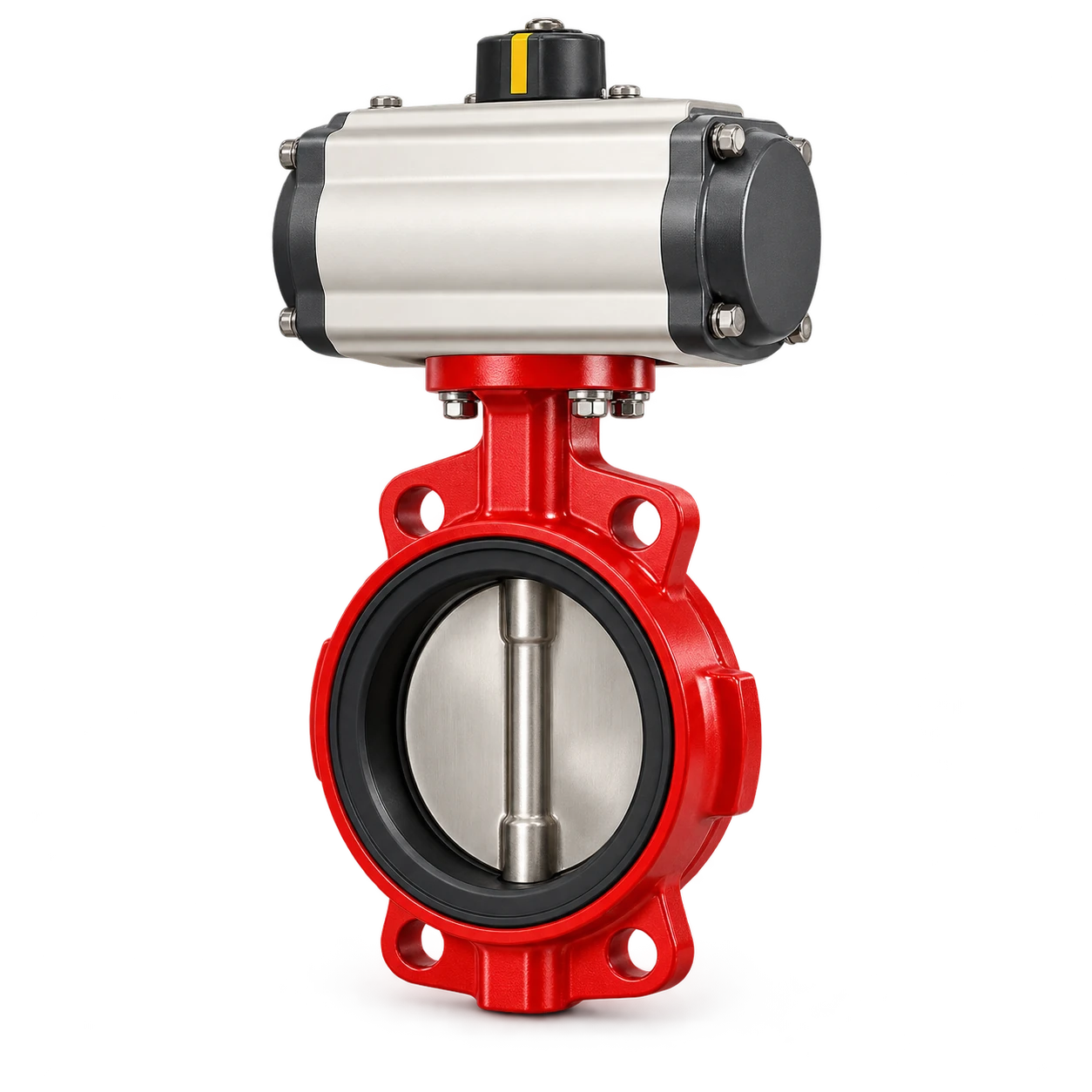
The rotary airlock maintenance guide provides a related method for mapping clearances and diagnosing leakage in a rotating discharge device. A slide gate has a different function: it generally interrupts or restricts the opening rather than metering through rotor pockets. For actuator interface questions, the butterfly valve actuator torque guide shows why mechanical compatibility and actuator capacity must be verified separately.
Conclusion
Sound bulk solids slide gate valve selection defines the function, material and worst load before choosing opening or actuator. Confirm loaded-closing capability, system pressure, sealing, wear, thrust, stroke, interfaces, feedback and energy isolation in writing. For catalog sizes and connection review, view the SG slide gate valve details.