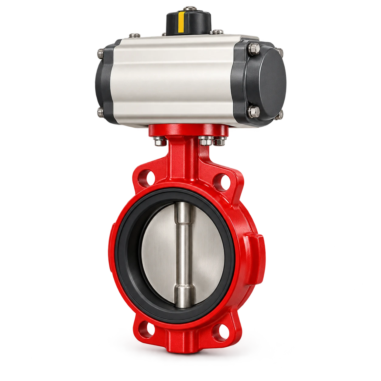

Rotary airlock valve maintenance should combine safe isolation, cleaning, measured clearance trends and inspection of the bearings, seals and drive. Do not diagnose air leakage from one generic gap value or diagnose a squeal from sound alone. The correct limits and service steps come from the supplied valve documentation and the actual material, temperature, pressure difference and operating history.
The YJD rotary airlock valve is a catalog range for metering and discharging powders or granules, with A and B flange configurations. Select it by inlet size, discharge rate, flange form and material. The current product data does not publish a universal rotor clearance, leakage rate, pressure rating or maintenance interval, so those items require order-specific confirmation.
Start with the duty record
A useful maintenance record describes what the valve is doing, not only its tag number. Capture:
- material, bulk-density range, particle size and abrasiveness;
- normal and upset material temperature;
- inlet condition, including whether the rotor is continuously flood loaded;
- upstream and downstream pressure and the differential across the valve;
- rotor speed, drive type, starts per hour and operating hours;
- required metering, discharge or airlock function;
- cleaning method and any washdown or corrosion exposure;
- last measured clearances, repairs and replaced parts.
If the valve sits below a hopper or silo under a continuous head of material, it is a feeder as well as a discharge device. Its speed and pocket volume do not by themselves guarantee mass flow: filling efficiency, material flowability, head load, venting and downstream pressure all influence the result.
Also define the system boundary. An enclosed rotary valve is not necessarily airtight or pressure rated. It is not an explosion-isolation device unless the complete supplied configuration has the required documented approval and is installed within that approval’s conditions.
Isolate every energy and material source
Before removing a guard, cover, drive or endplate, isolate the motor and any pneumatic or hydraulic auxiliaries. Prevent gravity-fed material from entering, relieve trapped pressure or vacuum, and secure any stored mechanical energy. Verify zero-energy state under the site’s procedure.
OSHA’s control-of-hazardous-energy guidance identifies electrical, mechanical, pneumatic and other energy sources as hazards during servicing. It specifically warns that unexpected startup or stored-energy release can cause serious injury. A local stop command, disconnected control signal or closed upstream gate is not by itself verified isolation.
Keep rotating shafts, couplings and chain or belt drives guarded during operation. OSHA’s machine-guarding overview states that machine parts, functions or processes capable of causing injury must be safeguarded. After work, reinstall the specified guards before a test run.
If internal access involves a hopper, chute or vessel, apply the site’s entry and engulfment controls. This article is not an entry procedure.
Clean before measuring
Product packed on a rotor tip can create an apparent clearance loss. A thin hard deposit on an endplate can also produce rubbing that looks like shaft movement. Clean by the manufacturer-approved method and inspect the removed material for metal, broken fasteners or foreign objects.
Record deposits by location:
| Finding | Possible process clue | Next check |
|---|---|---|
| Uniform coating | Adhesive or hygroscopic material | Temperature, moisture and cleaning interval |
| One-sided endplate buildup | Axial flow, misalignment or seal leakage | End clearance and shaft position |
| Local rotor-tip polish | Reduced local gap or distorted housing | Radial clearance map and bearing condition |
| Deep scoring | Foreign object or hard agglomerate | Upstream screen, process contamination and rotor damage |
| Material outside the seal | Seal wear, pressure or purge problem | Seal arrangement and pressure boundary |
Do not use a steel tool that can score a coated or machined surface. Do not grind a rotor in place to “make clearance” unless an approved repair instruction explicitly requires it.
Measure a clearance map
Clearance checks are useful only when the measurement positions and method are repeatable. Use the tools and access method named by the manufacturer. Identify the rotor blade, angular position, axial location, temperature and whether the drive is connected.
A practical record can include:
- rotor-to-housing gap for every blade at the top, sides and bottom;
- rotor-to-drive-end endplate gap for each blade;
- rotor-to-nondrive-end endplate gap for each blade;
- shaft axial movement and bearing play by the approved method;
- housing temperature at measurement;
- smallest, largest and change from the last inspection.
For a simple trend calculation, assume the smallest recorded gap at one defined position was 0.30 mm at commissioning and is 0.24 mm today.
change = 0.24 − 0.30 = −0.06 mm
relative change = −0.06 ÷ 0.30 × 100 = −20%
These are hypothetical values, not YJD limits. The decision must use the model-specific minimum, measurement uncertainty and operating temperature. A percentage alone is not a pass criterion.
ACS Valves’ technical FAQ collection links squealing with possible clearance, drive or foreign-object problems and recommends reference to the valve maintenance manual. The same page publishes a clearance value in an NFPA-related context; do not transfer that figure to a YJD valve or any other model without its documented design and approval basis.
Read the pattern, not only the average
The clearance pattern helps separate causes:
| Pattern | Likely checks |
|---|---|
| All radial gaps gradually increase | Abrasive wear, rotor-tip erosion or housing wear |
| One blade differs from the others | Bent or damaged blade, local buildup or prior repair |
| Drive-end gap small, opposite end large | Axial shift, bearing location or assembly error |
| Gap changes as the shaft rotates | Shaft runout, rotor eccentricity or bearing movement |
| Acceptable cold, rubbing hot | Thermal growth, process temperature or insufficient design allowance |
| Clearances stable but leakage rises | Seals, pressure difference, rotor filling or process connection leak |
Never force a seized rotor through a hard spot with the motor. That can damage blades, shaft, gearbox or housing and may turn a trapped object into a projectile hazard when opened.
Diagnose symptoms in a fixed order
For noise or vibration, first stop under the approved condition and isolate. Check foreign objects and buildup, then rotor freedom, bearing condition, shaft movement, coupling or chain alignment, gearbox mounting and fasteners. Compare the symptom with no-load and normal-load history only when the manufacturer and site procedure permit those tests.
For reduced discharge, verify that material reaches and fills the rotor. Look for arching, rat-holing, compacted deposits, venting problems, wrong rotation, lower speed, downstream backpressure and worn or damaged pockets. Increasing speed may reduce pocket filling and can worsen wear; it is not a universal capacity correction.
For air leakage, inspect the entire boundary: rotor clearances, shaft seals, endplates, flange gaskets, inspection covers and adjoining ductwork. Record the actual differential pressure. A rotary valve limits air transfer through moving pockets and clearances; it does not create a perfect seal.
ACS Valves’ resource library provides manufacturer-specific technical drawings, datasheets and service resources. Use comparable model-specific documents supplied with the installed valve before ordering replacement parts or setting a repair dimension.
Inspect bearings, seals and the drive
Bearings should be evaluated from lubrication condition, temperature and vibration trends, shaft movement and contamination—not from temperature alone. Follow the bearing and valve instructions for lubricant, quantity and interval. Overgreasing can also raise temperature or push contamination toward a seal.
Inspect shaft seals for product leakage, purge condition where fitted, wear surfaces and correct assembly. Confirm whether leakage is inward air, outward dust or process gas; each implies a different pressure condition and risk.
For the drive, check guard condition, fastener security, coupling element or chain wear, sprocket alignment, gearbox oil condition and torque-arm or base integrity. The drive may contain its own lubricant and mounting-position requirements. Do not assume the valve bearing grease is suitable for the gearbox.
The shaft-mounted gearbox installation guide explains alignment, reaction restraint and lubrication checks that are useful when reviewing adjacent drive equipment, although the YJD drive arrangement must follow its own approved documents.
Return the valve to service deliberately
Complete a closeout check before energizing:
- tools, loose parts and cleaning media removed;
- rotor turns only by the approved manual method and has no unexplained hard spot;
- endplates, seals and inspection covers correctly assembled;
- fasteners tightened by the documented method;
- lubricant and gearbox oil confirmed;
- direction-of-rotation check planned without exposed moving parts;
- all guards installed;
- upstream and downstream isolation restored in the approved sequence;
- local and remote controls, interlocks and overload protection tested;
- baseline noise, current, speed, temperature and leakage observations recorded.
Run unloaded only if the manufacturer permits it, then introduce material gradually under an approved commissioning plan. Stop if rubbing, abnormal current, repeated overload, fast temperature rise or visible seal failure appears. Do not “run in” metal contact unless the supplied instructions explicitly define that process.
Set an evidence-based maintenance interval
Calendar intervals should be adjusted from inspection evidence. Shorten the interval after a material change, higher temperature, greater pressure difference, foreign-object event, accelerated wear or an overload. Extend it only when the manufacturer permits and the trend data demonstrate stable condition.
A useful service record contains operating hours, throughput estimate, material, temperature, differential pressure, clearance map, bearing and seal findings, drive observations, photos, replaced parts and the next trigger. This makes maintenance a measurable condition decision rather than a repeated teardown with no history.
Conclusion
Rotary airlock valve maintenance is safest and most useful when isolation, cleaning and measurements follow a repeatable plan. Map rotor and endplate clearances, compare them with model-specific limits and previous readings, and interpret them together with deposits, bearings, seals, drive condition and system pressure. Do not treat a generic clearance, service interval or air-leakage claim as a YJD product specification.
For YJD selection or replacement review, provide the material, temperature, inlet size, required discharge rate, flange form, pressure conditions, drive controls and current inspection findings.