
Shaft-mounted gearbox installation succeeds when the reducer fits the driven shaft without forced assembly, the torque arm reacts load without binding, and the lubricant, guards and rotation are correct for the installed orientation. Prove those conditions before applying material. A drive that turns during a brief bump test can still overload bearings, loosen on the shaft or fail under belt tension.
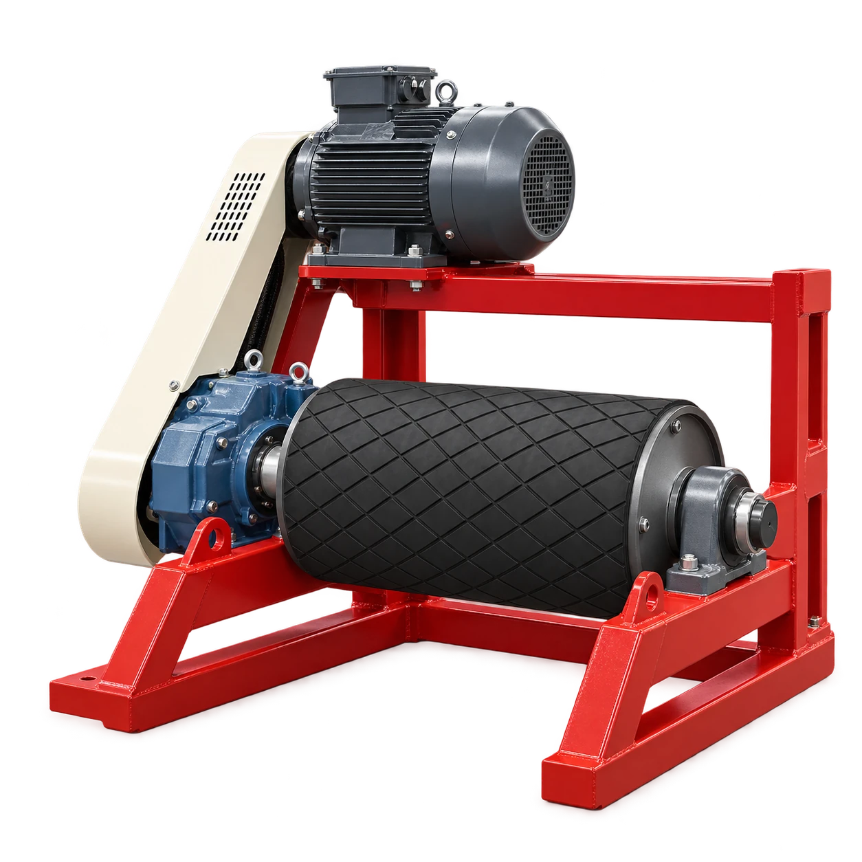
The belt conveyor drive frame combines a motor and shaft-mounted gearbox arrangement. Its product data says selection depends on belt load, speed, drive power and mounting arrangement. Those inputs define the drive package; they do not replace the exact reducer, motor and conveyor manuals used for installation.
Freeze the interface before shaft-mounted gearbox installation
Release the drive for installation only after the supplier and site agree on the interface schedule. Record rather than infer:
| Interface | Required evidence |
|---|---|
| Driven shaft | Diameter, tolerance, usable length, key dimensions, material and surface condition |
| Reducer connection | Exact bore, bushing or shrink-disc type, key requirement and tightening sequence |
| Axial location | Hub position, clearance to bearing housing and retention method |
| Torque arm | Approved attachment point, lever arm, joint type, fasteners and movement allowance |
| Drive orientation | Output-shaft direction, motor position, rotation, breather and drain access |
| Safety | Guard envelope, removable-panel fasteners, isolation points and maintenance clearance |
The NORD B1000 installation manual portal is an example of the model-specific documentation that must control fit-up, lubricant configuration and commissioning. Do not transfer a tightening torque, shaft tolerance or oil quantity from a different reducer family merely because both are described as shaft mounted.
Measure the shaft and mating component before assembly. Remove burrs and contamination without reducing the designed fit. Confirm whether the connection uses a parallel key, taper bushing or shrink disc; each transfers torque differently and has a different assembly sequence. Do not add an unapproved key, retaining screw or lubricant to a friction joint.
Mount the reducer without loading the conveyor bearings
Support the gearbox during installation so its weight does not hang from a partly engaged hub. Use the manufacturer’s approved pulling or jacking method. Hammering the housing or output hub can brinell bearings, damage seals and distort the interface.
Move the reducer to its specified axial position and verify clearance from the conveyor bearing housing, pulley end plate and guard. Axial retention must follow the approved design. The conveyor shaft should not be pushed through its bearings to make a mismatched hub location appear correct.
Before fitting the torque arm, the reducer should sit naturally on the shaft. If the arm must pull or twist the housing into position, stop and find the dimensional error. Possible causes include the wrong bushing, an incorrect shaft shoulder, a distorted support bracket or an off-location anchor.
The related WS shaft-mounted gearbox product is a useful procurement checkpoint for confirming output arrangement and ratio options. The installed model and its manual—not a generic product family description—remain the authority for assembly details.
Set the torque arm from reaction load and movement
The torque arm prevents the reducer housing from rotating while the output hub drives the shaft. It also has to tolerate the small movements allowed by its bushings and by the conveyor structure. A rigid, misaligned arm can transmit unintended radial or axial force into the reducer and pulley bearings.
For an initial load-path review, housing reaction force can be estimated as:
F = T / r
where T is gearbox output torque and r is the perpendicular distance from shaft center to the torque-arm reaction point. For a hypothetical 2,000 N·m output torque and 0.45 m lever arm:
F = 2,000 / 0.45 = 4,444 N
This is a calculation example, not VOGO product data and not a bracket design load. Starting, reversing, braking, belt jams, service factors, arm angle and joint stiffness can raise the real demand. Obtain the reducer supplier’s rated torque and mounting instructions, then have the support and fasteners checked for the governing load cases.
Install the approved bushings, pins and locking hardware. Confirm that the arm cannot foul the frame through its permitted movement. Never use the torque arm as a convenient lifting point or as a stop for belt take-up travel.
Configure lubricant for the actual mounting position
Reducer lubrication is orientation dependent. The correct fill volume, level port, drain and breather location may change when the drive is rotated around the conveyor shaft. Verify the reducer identification and mounting position against its manual before adding or checking oil.
The gearbox oil selection guide explains why an oil grade alone does not establish compatibility or quantity. For this installation, record the supplier-approved lubricant, fill quantity or level method, ambient range and first inspection interval. Remove any transport closure and fit the specified breather only when the manual instructs. An incorrect breather position can leak oil or allow pressure to build inside a gearbox that was not configured for that orientation.
Check for leakage after the first stationary fill, again after no-load running and after the loaded temperature stabilizes. Do not top up solely because oil is not visible at a port that belongs to another mounting position.
Guard and isolate the complete drive
The risk boundary includes the motor connection, input coupling or belt, reducer, output shaft, keys, torque arm pinch zones and conveyor pulley. OSHA’s mechanical power-transmission rule addresses exposed shafting, projecting keys, gears, pulleys, belts and couplings. Applicable local requirements may differ or add obligations.
Design the guard so routine inspection does not invite reaching through an opening. Fasteners, access panels and clearances must suit the site’s risk assessment. CEMA publishes conveyor safety resources that can support the site’s labeling and training program, but labels do not replace physical safeguards.
Work behind a removed guard is servicing. Apply the site’s hazardous-energy procedure to electrical power, stored belt tension, gravity, backstop forces and any downstream movement. OSHA’s lockout/tagout overview makes clear that stopping equipment is not the same as controlling unexpected energization.
Commission in controlled stages
Use a signed record rather than a single “runs OK” box:
- Verify fasteners, hub engagement, axial clearance, torque-arm joints, oil configuration and guard completion.
- Confirm electrical phase sequence and intended pulley direction using the approved safe method. A backstop, if fitted, must agree with rotation before powered testing.
- Run without conveyed material for the duration specified by the drive supplier. Observe noise, leakage, guard contact, torque-arm movement and belt tracking.
- Record motor current, reducer surface temperature and vibration at repeatable points; these are baselines, not universal acceptance limits.
- Add load in controlled steps while checking belt tracking, pulley slip, structural movement and protection settings.
- Stop, isolate and inspect the shaft connection and torque-arm hardware at the supplier’s required interval.
If temperature or vibration rises quickly, do not keep running merely to obtain a trend. Stop under the agreed criteria and inspect lubricant setup, shaft fit, torque-arm binding, belt tension, pulley alignment and load. If motor current rises only with material, also confirm that actual belt load and lift match the design basis.
Conclusion
Shaft-mounted gearbox installation is an interface-control task, not simply sliding a reducer onto a shaft. Match and measure the connection, place the housing without bearing preload, install the torque arm on the approved load path, configure lubricant for orientation, complete guarding and verify operation in stages. Preserve the measurements and baseline readings for maintenance.
For a drive-frame review, provide the belt load, speed, pulley shaft drawing, duty cycle, mounting envelope, power supply and required safeguards.