
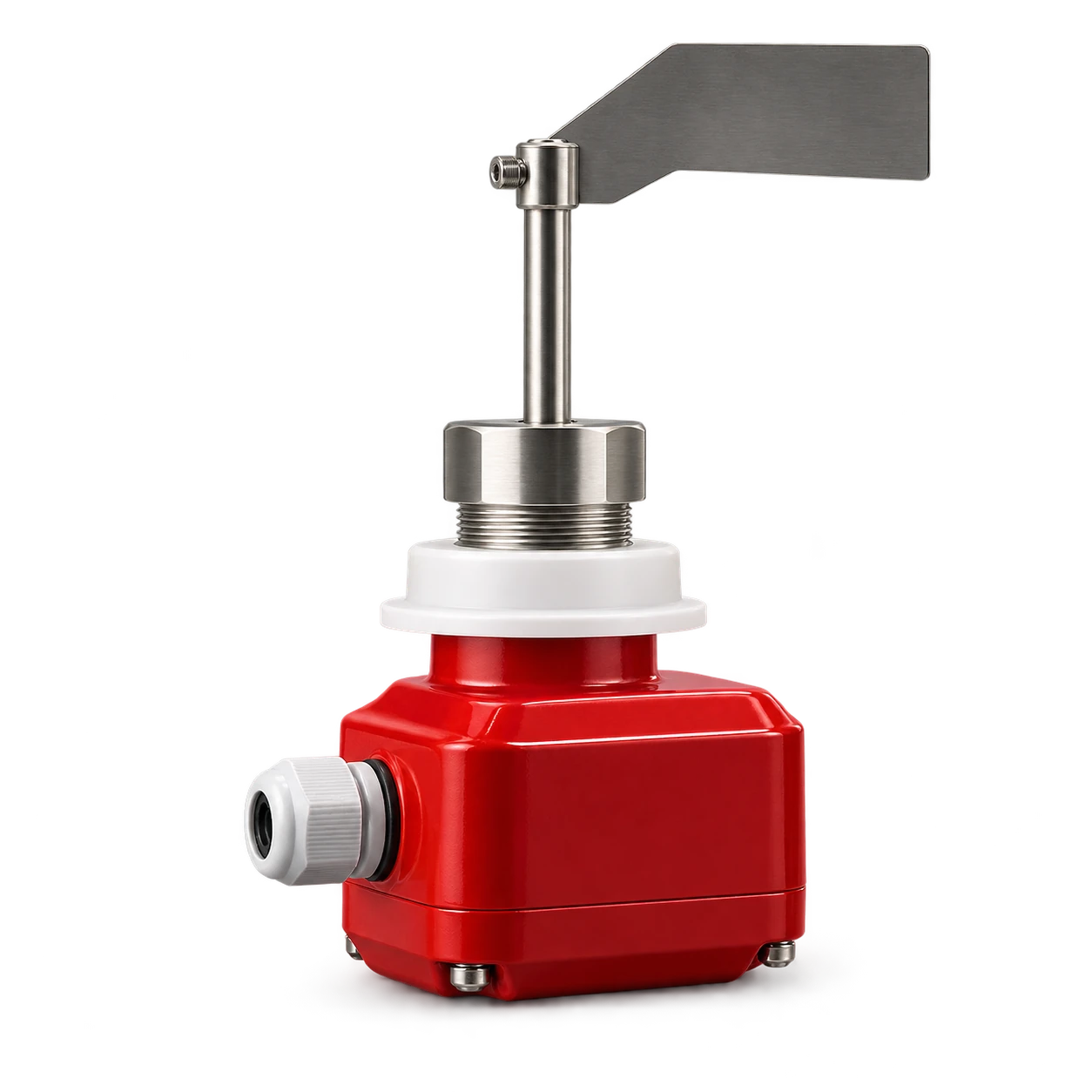
A rotary paddle level switch installation must put the paddle at a representative point where material can stop it reliably, while protecting it from the filling stream and excessive mechanical load. Then the complete signal path must be tested: uncovered, covered, power lost, alarm received and interlock acted. The device is a point switch, not a continuous inventory measurement.
The rotary paddle level indicator is specified from the material, mounting direction, probe length and control voltage. Confirm those four inputs before ordering. The catalog identifies the product and selection basis but does not authorize a universal paddle, sensitivity setting or wiring scheme.
Define the level-switch duty first
Write one clear functional statement, such as: “Detect cement at the high operating level and stop the filling permissive after the configured control delay.” Avoid the vague tag “silo level.” A rotary switch can serve different duties:
| Duty | Normal process state | Required control decision |
|---|---|---|
| High level | Paddle normally uncovered | Alarm or stop filling when covered |
| Low level | Paddle normally covered | Alarm or stop discharge when uncovered |
| Backup high-high | Normally uncovered | Independent protective response at a higher point |
| Chute blockage | Normally uncovered | Stop upstream feed when material persists |
Monitor Technologies explains the operating principle on its KA/KAX rotary paddle page: the motor turns the paddle while it is free; material that impedes rotation changes the switch state and stops the motor. BinMaster’s BMRX-100 manual page describes the same point-detection distinction. These are examples from other manufacturers, so their speeds, relays and settings must not be assumed for the VOGO device.
Decide what power failure means before selecting the relay logic. For a high-level duty, the control system may need a fault when power or signal continuity is lost rather than interpreting loss as “not full.” That behavior depends on the exact device contacts, PLC wiring and site safety analysis. Document energized and de-energized states; do not label a circuit fail-safe without proving the complete loop.
Choose a representative mounting position
The switch sees only the material at its paddle. A poor position can leave the paddle uncovered while a pile reaches another part of the roof, or keep it buried in a stagnant wall zone after the usable inventory has fallen.
Review the expected filling pattern, angle of repose, outlet flow pattern, internal bracing, aeration and cleaning method. For a high-level switch:
- keep the paddle away from direct impact under the fill pipe;
- avoid a sheltered pocket behind a stiffener or pipe;
- leave access for removal without entering the vessel;
- keep the alarm point below the maximum safe fill boundary and required freeboard;
- account for material buildup that can hold the paddle after the bulk level falls.
For a low-level switch, avoid a location that can remain covered by a wall shelf while the outlet starves. If arching or rat-holing is possible, the switch reports local material presence; it does not correct the flow problem. Hopper geometry, outlet size, moisture, compaction and flow aids must be evaluated separately.
The silo dust collector sizing guide covers filling-air and venting duty. A high-level switch complements those controls but is not a filter, pressure monitor or relief device.
Match probe and paddle to the material
Give the supplier representative bulk-density range, particle size, flowability, temperature, moisture tendency and whether material can pack or build up. The exact paddle area and any sensitivity adjustment must come from the selected device manual.
Monitor’s KA/KAX manual provides model-specific guidance for paddles, mounting and sensitivity. BinMaster’s BMRX-300 manual page likewise documents options and operation for its own product. Their published limits illustrate why “rotary paddle” is not a complete specification; do not copy one brand’s material-density limit, extension arrangement or torque setting to another.
For top mounting, select an extension that reaches the required elevation and is supported as the manufacturer specifies. For side mounting, consider cantilever load from the paddle, accumulated material and cleaning. A protective shield may be appropriate against falling material, but it must not create a pocket that prevents representative contact or traps material permanently.
Confirm the process connection, insertion clearance and orientation before cutting the vessel. Welding near an installed instrument can damage electronics and seals. Any nozzle, coupling or reinforcement must suit vessel structure and site rules; the level switch itself does not make the silo pressure rated.
Install without creating a false mechanical signal
Isolate filling, discharge, aeration and any internal mechanical equipment before opening a connection or placing hands near the paddle. OSHA’s hazardous-energy guidance covers unexpected energization and stored energy during servicing. Vessel access may also trigger confined-space and material-engulfment controls under applicable site rules.
Before installation:
- compare the device nameplate with supply voltage and area classification requirements;
- verify probe length, paddle, process connection and mounting orientation;
- inspect the shaft for shipping damage and free movement using only the manual-approved method;
- route conduit so it does not load the housing and so water cannot drain into entries;
- preserve access to terminals and future removal clearance.
Tighten the process connection by the approved flats or mounting hardware, not by twisting the enclosure. Orient cable entries and covers to maintain the specified environmental protection. A closed enclosure is not automatically airtight, pressure rated or approved for a hazardous location.
Wire a state table, not an assumption
Use the device wiring diagram and make a four-state table before PLC programming:
| Test state | Local device indication | Relay/contact state | PLC tag | Required response |
|---|---|---|---|---|
| Powered, paddle free | Record actual | Record actual | Normal | Filling/discharge permitted as designed |
| Powered, paddle impeded | Record actual | Record actual | Level detected | Alarm or interlock after approved delay |
| Device power lost | Off or fault | Record actual | Fault state | Site-defined safe response |
| Signal wire open | Device may remain powered | Input fault or changed state | Fault state | Maintenance alarm and safe response |
Do not infer normally open or normally closed behavior from the words “high level.” Verify terminal numbers and switching action on the supplied unit. Where a time delay is used to reject momentary splashes or falling material, record its purpose and prove that the resulting response time still protects the process.
Keep power and signal wiring within the manufacturer’s ratings and local electrical code. Ground the enclosure as required. If a hazardous dust location applies, every component—including cable entries, junction boxes and installation practice—must have the required approval; the ordinary presence of a sealed cover is not evidence of certification.
Proof-test the complete protective function
A bench test proves only part of the chain. Commission under a controlled permit with the process owner, electrician and control technician:
- Confirm the uncovered state and the HMI indication.
- Use the manufacturer’s safe method to impede the paddle; never grab an energized rotating paddle.
- Confirm motor stop and contact transfer where applicable to that model.
- Verify PLC tag, alarm text, horn or beacon and event timestamp.
- Prove the upstream filling or downstream discharge interlock under an approved simulation.
- Remove device power and open the signal circuit separately to verify fault handling.
- Restore the system and confirm that reset does not create an unexpected automatic restart.
- When process conditions allow, compare the installed response with actual material coverage.
Record the time from simulated detection to the final controlled action. This is a system measurement, not a universal sensor rating. If the action is too slow, separate mechanical switch response, configured delay, PLC scan/logic, communication and actuator stopping time before changing settings.
For overfill protection, define what happens after the switch operates. Material already in the fill line can continue moving. A relief device such as the RV pressure relief valve serves a different function and cannot be replaced by a level alarm; likewise, a relief valve does not prevent overfilling.
Diagnose inconsistent switching
| Symptom | Check first |
|---|---|
| Never changes state during filling | Wrong elevation, short probe, wiring error, unsuitable paddle or material bypassing location |
| Remains covered after discharge | Buildup, stagnant wall zone, bent shaft or packed material around shield |
| Chatters during filling | Direct fill-stream impact, unstable pile surface, loose mounting or excessive control sensitivity |
| Works locally but not in PLC | Contact selection, common terminal, supply, input type, broken conductor or logic inversion |
| Frequent mechanical damage | Unsupported extension, falling lumps, side load, cleaning impact or unsuitable mounting arrangement |
Do not cure repeated alarms by extending a PLC delay until the alarm disappears. First establish whether the switch is seeing real process behavior, mechanical impact or an electrical fault.
Conclusion
Rotary paddle level switch installation begins with a defined point-level duty and a representative location. Match the paddle and probe to the real bulk solid, protect the assembly from impact, document every electrical state and prove the complete alarm or interlock—including power loss. Treat silo flow, venting and pressure protection as separate system functions.
For product selection, provide the material, duty, mounting direction, probe length, control voltage, process connection and required alarm response.