Fine, aeratable powders such as cement, fly ash, and silica fume require specific equipment in bulk solids processing. Unlike granular materials, these fine powders fluidise easily when aerated and cause unpredictable flow, flooding, and inaccurate metering. Engineers use specialised screw feeder and conveyor designs to manage these behaviours. The variable pitch screw flight, specifically the reducing pitch configuration, compresses the powder, removes trapped air, and meters volume precisely.
A standard screw conveyor with a constant pitch transfers material. When used as a feeder directly beneath a silo or hopper, or when discharging into a pressurised system, a constant pitch design causes ratholing, erratic flow, and air migration. Varying the flight pitch allows process designers to change the bulk density, control aeration, and form a mechanical seal. The engineering analysis of reducing pitch screw flight design covers mechanical principles, material behaviour, torque distribution, and practical design guidelines for cement and powder plants.
The mechanics of reducing pitch screw flight design
Pitch is the axial distance between consecutive flights in a screw feeder or conveyor. This distance remains constant in a standard conveyor but changes along the screw length in a variable pitch design. Some screw feeders utilise an increasing pitch towards the discharge to draw material evenly from a wide hopper inlet and prevent ratholing. A reducing pitch compresses and deaerates the material.
A reducing pitch decreases the axial volume available for the material with each revolution. The screw is typically flood-loaded at the inlet, so the mass flow rate must remain constant. The reduction in volumetric capacity per flight forces the powder to compress. The flights push the material into a tighter space. This increases the bulk density and reduces the interstitial voids between particles.
Mechanical compression is the primary engineering objective of this geometry. Squeezing the powder expels trapped air in a process called deaeration. The powder changes from a loose, aerated state to a dense, compacted state. This alters the flow characteristics and creates a cohesive, predictable solid stream. Controlled densification is necessary for applications requiring precise loss-in-weight metering or a transition between atmospheric and pressurised zones.
Material behaviour: deaeration and airlock function
Fine powders like cement and fly ash tend to retain air. When discharged from a silo, these materials carry interstitial air that makes them behave like a liquid in a process called fluidisation. If fluidised powder enters a weighing hopper or downstream process, it causes batch overshoot, inaccurate dosing, and long settling times.
The reducing pitch screw reduces fluidisation through deaeration. As the flights compress the material, expelled air moves backwards through the voids in the powder bed and escapes through the inlet or dedicated vent points. At the discharge, the powder is densified. This reduces fluid behaviour and maintains a consistent gravity flow into the receiving vessel.
The compressed material at the discharge end of a reducing pitch screw is an airlock. In systems where the screw feeds into a pneumatic conveying line or a pressurised mixer, the compacted powder plug creates a mechanical seal. This seal prevents high-pressure air from downstream equipment from bypassing the screw and blowing back into the upstream silo. Without this airlock, reverse airflow would fluidise the material inside the screw, destroying metering accuracy and causing dangerous dust emissions at the inlet.
Torque distribution and motor sizing considerations
Powder compression increases the load on the drive system. A constant pitch conveyor distributes torque relatively evenly, and the highest load occurs at the drive end because of the cumulative weight of the material and shaft. In a reducing pitch screw, the torque profile changes.
As the material compresses, rotational resistance increases towards the discharge end. The highest torque occurs in the final, most tightly pitched section of the screw. Here, the powder reaches maximum density and friction against the trough or tube is highest. The shaft must withstand high torsional stresses at the discharge end, and the drive system must handle this peak load.
Motor sizing for a reducing pitch screw cannot use standard constant-pitch calculation methods. Engineers must account for the extra work needed to compress the material and overcome the increased friction of the densified powder. Standard motors, such as 3-phase, 380 V, 50 Hz, 4-pole, 1,450 rpm configurations, are common prime movers. The gear reducer ratio and service factor must be selected to provide sufficient output torque at the required low operating speeds. Starting torque also requires evaluation. If the screw stops while fully loaded, the compressed material can solidify or pack tightly. The motor and drive system must overcome this high static friction without tripping.
Practical design guidelines for fine powders
Designing a variable pitch screw for powder compression depends on the specific characteristics of the bulk solid. For cement, fly ash, and similar fine powders, apply the following guidelines.
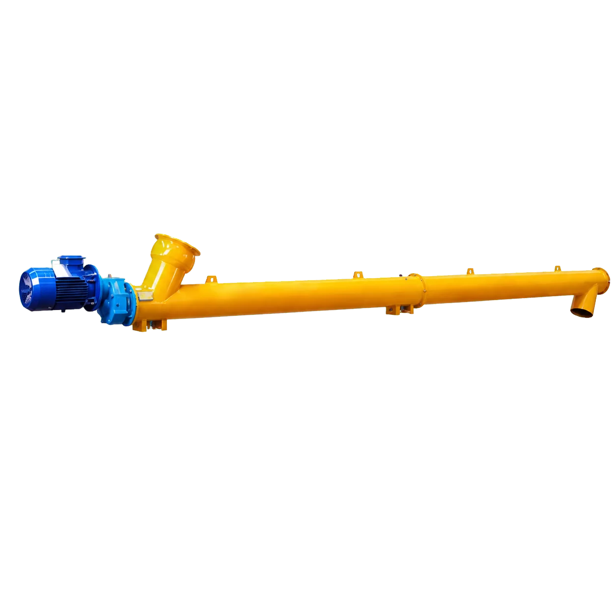
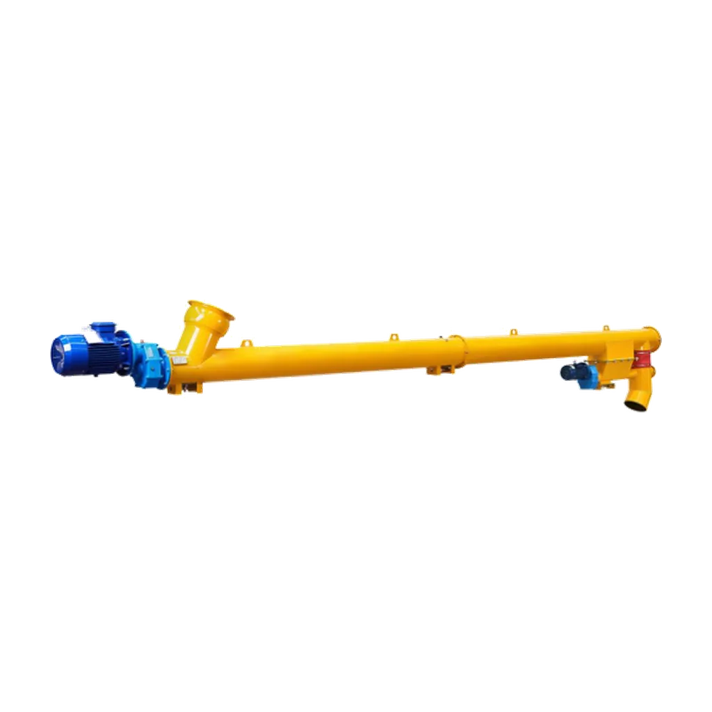
Use a tubular screw conveyor configuration. A rigid tubular body keeps the conveying path compact, limits external dust exposure, and contains the pressures generated during material compression. The enclosed tube maintains deaeration and allows the airlock seal to function correctly.
Calculate the degree of pitch reduction precisely. An aggressive reduction causes excessive power consumption, rapid flight wear, and potential material degradation or overheating. A gradual reduction fails to deaerate the powder or form a sufficient airlock seal. The pitch ratio (inlet pitch to discharge pitch) depends on material compressibility, initial bulk density, and the required pressure differential across the screw.
Design the screw feeder inlet for 100 per cent flood loading. A starved inlet prevents the compression zone from forming and causes the airlock to fail. This requires specific hopper geometries, such as mass-flow bottoms, to provide a steady material supply to the screw.
Actual capacity and power depend on the moisture, particle size, and bulk density of the conveyed material, so use published capacity ranges only as a selection reference. Each project requires a specific calculation to confirm the exact diameter, length, pitch profile, and drive arrangement needed for the duty.
Conclusion
A reducing pitch screw flight design controls the flow of fine powders by compressing the material. This compression deaerates the powder, prevents fluidisation, and creates a reliable airlock seal. These functions enable precise metering and stable operation in cement and fly ash handling. The increased mechanical resistance requires engineers to account for shaft torque distribution, motor sizing, and overall system configuration.
When specifying equipment for these applications, engineers should work with manufacturers who understand powder behaviour. VOGO Machine supplies project-specific Cement Screw Conveyors, including enclosed tubular designs for compression and metering duties. The conveyors are available in multiple diameters with customisable drive and connection arrangements to match specific process requirements. To review selection parameters or download the datasheet, visit the VOGO Machine Cement Screw Conveyor product page.