
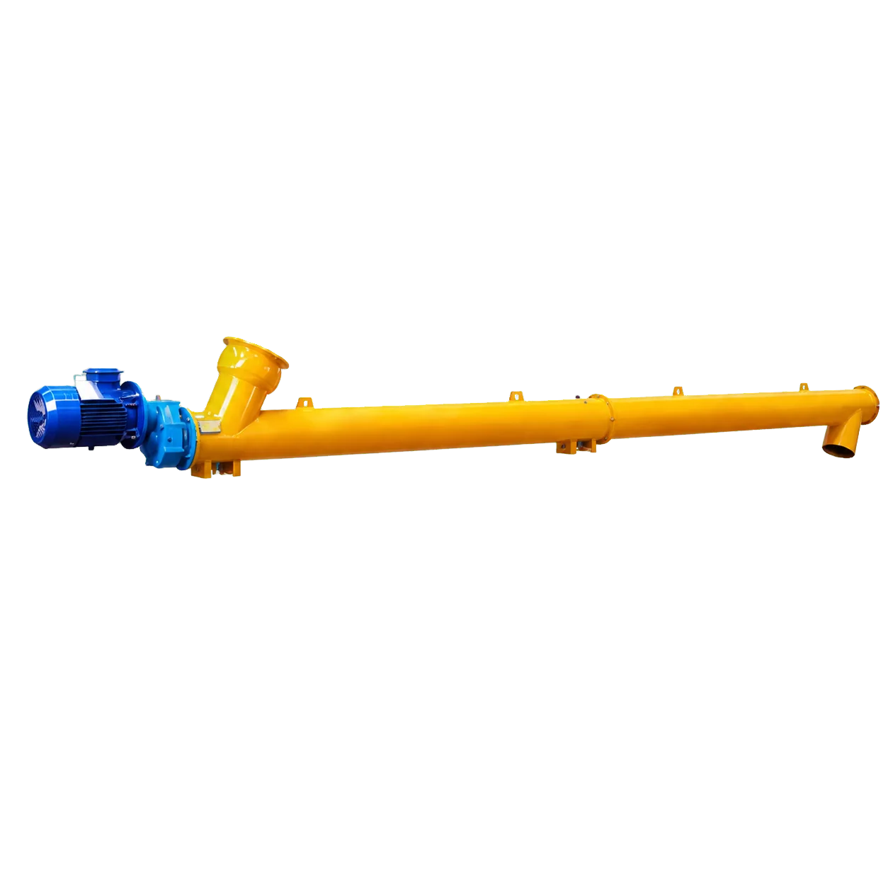
Screw conveyors move powders and granules reliably in cement production, dry-mix mortar manufacturing, and bulk material handling. The basic design, a rotating helical screw inside a rigid housing, is simple. However, when a process requires elevating material between stages, horizontal sizing assumptions no longer apply. The inclination angle changes the physics of material movement by introducing gravity as a direct opposing force.
Mechanical engineers and process designers must account for the effect of inclination on screw conveyor capacity. An inclined conveyor pushes material forward while lifting it against gravity. This action causes material to slide or flow backward between successive flights, reducing the net volume reaching the discharge end. Ignoring this efficiency loss leads to undersized equipment, missed throughput targets, and overworked drive motors.
The mechanics of inclined conveying and efficiency decay
In a horizontal screw conveyor, gravity keeps material settled in the lower section of the trough or tube. The rotating screw flight pushes it steadily towards the discharge. When the discharge end is raised, the conveyor centreline forms an angle with the horizontal. Gravity then works against the conveying direction. The screw flight still pushes material forward, but some of it slides or flows backward into the space behind the previous flight.
The theoretical volume trapped between the flights no longer equals the actual amount of material reaching the outlet. This fallback effect increases with the steepness of the incline. For inclines up to 10 degrees, capacity reduction is minimal. Between 15 and 30 degrees, the loss is significant and often requires design adjustments. For axial tubular screw conveyors handling typical powders, the inclination angle is usually limited to about 45 degrees. Beyond this angle, material tumbles backward instead of being lifted, which reduces efficiency and increases wear on internal components.
Inclination should not be treated as a single, fixed capacity correction factor for all machines. Two conveyors operating at the same angle can perform differently. Efficiency decay depends on several variables, including the material’s flowability, screw flight pitch, housing structure, inlet loading conditions, and rotational speed. The main engineering consideration is whether the selected configuration can maintain the required capacity at that specific angle under actual material and feeding conditions.
Capacity calculations and compensation strategies
Sizing an inclined screw conveyor requires a baseline capacity calculation. The standard volumetric capacity formula for a horizontal screw conveyor is Q = (π/4) × D² × P × n × ρ × φ × 60. In this equation, Q is the capacity in tonnes per hour, D is the screw outside diameter in metres, P is the flight pitch, n is the rotational speed in RPM, ρ is the material bulk density, and φ is the filling factor, the cross-sectional area of the trough filled with material.
When a conveyor is inclined, the effective filling factor (φ) decreases because material falls back between the flights. Engineers must adjust other variables in the equation to meet the target throughput. Common compensation strategies include:
- Increasing the rotational speed (n) maintains the mass flow rate, though excessive speeds cause the material to tumble or aerate.
- Using a shorter screw flight pitch (P) adds more lifting faces per unit length to grip the material and reduce backward sliding.
- Selecting a larger screw diameter (D) increases the overall conveying volume and adds a safety margin for the lost efficiency.
- Upgrading the drive system is necessary because the motor and gear reducer must supply additional power to lift the material column vertically and overcome horizontal friction. Starting torque increases significantly, so the drive components must prevent stalling under a full load.
Specifying an excessively large inclination angle is a common error. Optimising the screw geometry and drive configuration for the specific site conditions is more effective than forcing a standard horizontal design to operate on a steep slope.
Material characteristics and the VOGO approach
Compensation strategies depend on the properties of the conveyed material. In cement batching, fly ash transfer, and dry mix mortar applications, the materials are fine, dry powders with bulk densities of 0.5 to 1.0 t/m³. These powders flow freely and allow higher filling factors in horizontal applications. On an incline, this free flow worsens the fallback effect if the screw geometry is not optimised.
Cement and similar powders can become aerated and behave like a fluid. Aerated material flows backward easily on an incline. The enclosed, rigid tubular body of the conveyor prevents this. A well-sealed tubular design keeps the conveying path compact, limits external dust exposure, and maintains the inlet pressure head required to push the material upward.
Conveyors require configuration for each project. Each unit must match the specific material, bulk density, moisture content, required throughput, centreline length, and inclination angle. Correct hanger bearings, end bearings, and drive arrangements allow the equipment to handle the increased mechanical stresses of inclined operation. The rigid tubular construction keeps internal clearances stable and prevents material from bypassing the flights.
Conclusion
Inclining a screw conveyor reduces its effective capacity because gravity causes material to fall back. Horizontal conveyors run at maximum volumetric efficiency. Inclined conveyors need adjusted rotational speeds, modified flight pitches, or higher drive power to compensate for the loss in capacity. Engineers must account for the flow characteristics of cement and dry powders to prevent aerated fallback and maintain stable throughput.
VOGO Machine designs cement screw conveyors to handle these physical constraints. Our tubular screw conveyors come in diameters from Ø89 mm to Ø407 mm. We configure each unit to match the specific inclination, length, and material requirements of the project. The published catalog capacity range of 1.3 to 170 t/h is a selection reference. Actual capacity and power depend on the material, filling degree, inclination, and operating conditions, and must be confirmed for each project. To check the selection parameters and find the right configuration for your plant layout, visit the VOGO cement screw conveyor product page or download the datasheet for engineering specifications.