
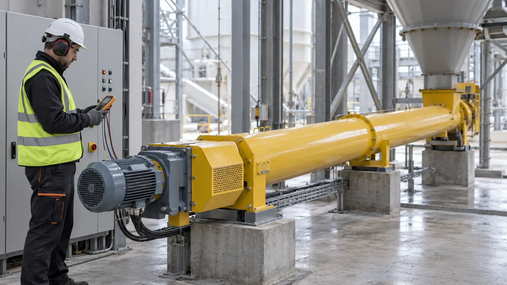
Cement screw conveyor reverse rotation should be treated as a commissioning fault unless the machine was explicitly designed, documented, and controlled for bidirectional duty. If the screw turns the wrong way after electrical work, stop it, prevent cement from entering, isolate the energy sources, and verify the required shaft direction against the approved drawing and flight hand. Do not use reverse jogging as a shortcut for clearing a blockage.
The VOGO tubular cement conveyor range is configured around the material, flow, geometry, and interfaces stated for a project. The published product data does not claim that every unit is reversible, that reverse operation is an included control function, or that direction monitoring is standard. Bidirectional duty must therefore appear in the enquiry, approved drawing, motor-control description, and acceptance test.
This article addresses a wrong-direction event and the engineering checks for intentional reversing. It does not replace the motor, VFD, reducer, coupling, or conveyor manufacturer’s instructions.
Cement screw conveyor reverse rotation: first decision
Before touching a parameter or terminal, decide which of three cases exists:
| Observed condition | Engineering interpretation | Immediate response |
|---|---|---|
| The screw turns opposite to the approved discharge direction after installation or electrical maintenance | Commissioning or change-control fault | Stop, block material feed, isolate, and reconcile mechanical and electrical documents |
| An operator wants to reverse a stalled screw to free cement | Unapproved recovery method unless a written design and procedure say otherwise | Do not jog; isolate and diagnose the blockage |
| The process specification calls for discharge to either end | Purpose-designed reversible duty | Review flight geometry, inlet, outlets, drive, controls, stopping sequence, and protection as one design |
The first two cases should not be converted into the third by adding a reverse pushbutton. A screw that can rotate in both directions electrically is not necessarily a conveyor that can transport the material safely and predictably in both directions.
Confirm direction from the mechanical arrangement
Do not rely on a motor fan, a VFD display, or the words “forward” and “reverse” on a selector. Those labels describe a control convention; they do not prove where the screw carries material.
Start with the approved general arrangement and screw assembly drawing. Identify the drive end, the intended inlet and discharge, the flight hand, and the viewing direction used by the drawing. Mark the required rotation on the commissioning sheet in unambiguous terms, for example “clockwise viewed from the drive-end shaft face.” Confirm that the installed screw sections match the drawing and that no section has been assembled with an unintended hand or orientation.
Then trace the drive train. The motor shaft, gearbox output, coupling, chain drive if present, and screw shaft may not share the same apparent direction when viewed from different ends. A technician who checks from the opposite side can report a correct rotation as wrong. Record one defined viewing point and, where safe, use an external guarded reference on the final driven shaft.
The cement screw conveyor installation and alignment guide covers the wider mechanical checks. Direction verification is one hold point within that process, not a substitute for confirming supports, bearings, clearances, coupling alignment, and free rotation.
Separate motor phase sequence from conveyor proof
For a conventional three-phase induction motor connected directly to the supply, the phase sequence establishes shaft direction. The ABB low-voltage motor manual defines direction from the drive-end view for its stated terminal arrangement and explains that interchanging two line connections changes direction. That is a motor-specific instruction, not permission to swap conductors on an energized or undocumented installation.
With a VFD, “forward” is set by the drive’s command source, parameterization, and output phase sequence. Changing line-side phases is not a general method for reversing VFD output. Follow the installed drive manual, approved schematic, and site electrical procedure. Check remote and local commands, two-wire or three-wire logic, fieldbus direction bits, parameter backups, safety functions, and any reverse-inhibit setting. A software command can be correct while motor leads are transposed, or the wiring can be correct while the command mapping is wrong.
Phase-sequence supervision is useful at the motor-control level. For example, the ABB M10x user guide describes voltage and current phase-sequence detection and an associated trip. Such protection must be configured and commissioned for the actual starter circuit; its presence cannot be assumed from the word “motor protection.”
Finally, prove the conveyor shaft. A contactor auxiliary contact or VFD run status confirms a command path, not screw movement. A pulse-based zero-speed switch confirms movement only at its sensing point. If the device counts identical targets, the same pulse frequency may occur in either direction. The zero-speed switch setup guide explains how to choose a representative shaft and test the motion-proof chain; directional proof needs a sensor arrangement and logic that actually distinguish direction.
Use a guarded no-load direction test
The preferred commissioning test prevents material from entering and keeps every rotating part guarded. The exact method must come from the site risk assessment and equipment manuals, but the evidence package should cover these steps:
- Confirm that construction is complete, guards are fixed, fasteners are accounted for, tools are removed, and personnel are clear.
- Positively prevent upstream material entry. A closed control signal alone is not enough if a valve can leak, a hopper can gravity-feed, or another system can start automatically.
- Confirm that the casing is empty or in the approved test condition and that the screw turns freely using the manufacturer’s isolated inspection method.
- Compare electrical phase sequence, terminal records, VFD parameters, starter logic, and the mechanical direction statement.
- Energize only under the approved commissioning permit and make the shortest test that reliably establishes final-shaft direction without opening a guard.
- Stop, isolate when adjustment is needed, correct the identified cause, and repeat the test.
- Record viewing point, direction, test mode, witnesses, electrical readings, parameter backup, and drawing revision.
HSE’s machinery safety guidance calls for machines to be properly switched off, isolated, or locked off before blockage removal, cleaning, or adjustment, and it prioritizes fixed guarding where practical. OSHA’s hazardous-energy guidance likewise addresses unexpected energization and stored-energy release during servicing. A stopped motor is not proof of isolation.
Do not reverse a blockage by trial and error
Reverse jogging can move the hazard rather than remove it. Cement may be compacted against the opposite end, pushed back into an inlet, released unexpectedly into an upstream vessel, or loaded into a section that was not designed as a discharge. Rapid forward-to-reverse commands also introduce torque reversals that must be checked against the reducer, couplings, keys, shafts, and fasteners. These are reasons for engineering review, not predictions that every reverse event will cause the same damage.
When the conveyor trips or stalls, first stop upstream flow and apply the site isolation procedure. Determine whether the initiating condition was a downstream restriction, foreign object, wet or consolidated cement, full casing after a process upset, failed bearing, misalignment, damaged flight, incorrect speed command, or loss of a material-flow interlock. The blockage causes and prevention article provides the broader diagnostic path.
Do not claim that changing rotation cures arching, rat-holing, or bridging above a silo outlet. Those behaviors depend on hopper geometry, outlet dimensions, wall friction, moisture, consolidation, aeration or other flow aids, and feeder withdrawal. The screw is one part of that system.
Treat flood-loaded equipment as a screw feeder
A screw mounted directly below a hopper, bin, or silo with a continuously flood-loaded inlet performs screw feeder duty. A normal screw conveyor is control-fed by an upstream valve or separate feeder. This distinction matters sharply when reverse rotation is proposed.
An ordinary flood-loaded feeder commonly uses increasing or variable pitch, tapered outside diameter, or another mass-flow withdrawal arrangement so available conveying volume changes along the inlet. Its geometry normally has one intended direction. KWS explains in its reversible screw feeder engineering note that variable-pitch inlet geometry is not automatically suitable for reversing. Its described central-inlet design requires material flow to be stopped, the feeder to clear, and the drive to stop completely before counter-rotation; it also uses a shroud beyond the inlet. These details illustrate the additional design problem, not a universal VOGO configuration.
For silo duty, review head load, loaded starting torque in each permitted direction, VFD low-speed torque, motor cooling, gearbox service factor, mechanical torque limits, overload or stall protection, and the ability to isolate the inlet. Do not apply a control-fed conveyor capacity table to the flood-loaded feeder. Reduced pitch alone is not a complete inlet design answer.
Specify intentional reversible duty before purchase
If the process genuinely needs two-way conveying, send suppliers a duty statement rather than asking whether the motor can reverse. Include:
- material identity, bulk-density range, moisture, temperature, flowability, and consolidation time;
- required capacity in each direction and whether both outlets can receive material safely;
- inlet position, inlet length, outlet positions, isolation valves, and expected residual inventory before reversal;
- normal and upset fill states, start frequency, stop-to-reverse delay, and permitted clearing sequence;
- screw hand, pitch or outside-diameter progression, shrouds, gates, and any unequal geometry by direction;
- continuous, start, stall, and reversal torque limits for the motor, VFD, reducer, couplings, shafts, and fasteners;
- direction commands, permissives, reverse inhibit, actual-direction feedback, upstream and downstream interlocks, and fault reset authority;
- guarding, access, hazardous-area conditions, pressure boundary, leakage target, and isolation procedure;
- witnessed factory and site tests for both directions.
“Enclosed” does not mean airtight, dust-free, or pressure-rated. Reversing may change which end sees material pressure or which connection becomes a discharge. Define seals, flanges, vents, flexible connections, operating pressure, and leakage acceptance for both directions.
A practical acceptance record
For a hypothetical control-fed conveyor that must normally carry cement from inlet A to outlet B, the acceptance sheet might state: “Required screw rotation: clockwise viewed from the drive-end shaft face; reverse command disabled in production; upstream rotary valve proven stopped before test.” After a guarded empty bump test, the team records actual direction, motor phase sequence, VFD parameter checksum, final-shaft motion indication, current, abnormal noise, and stop time.
If the shaft turns counterclockwise, no cement is introduced. The electrical team isolates the circuit, identifies whether the fault lies in output phase order or command mapping, applies the equipment-specific correction, and repeats the same witnessed test. Only after direction, guards, interlocks, and downstream readiness pass does controlled material commissioning begin.
That record separates verified facts from assumptions. It also prevents a later panel replacement or cable reconnection from being accepted merely because the motor starts.
Conclusion
Cement screw conveyor reverse rotation is safe to accept only when actual shaft direction matches the approved mechanical duty and the electrical controls have been verified under a guarded procedure. Wrong direction after wiring is a fault to correct before adding cement; reverse jogging is not a general blockage remedy. If bidirectional flow is required, specify a reversible conveyor or feeder as a complete mechanical and control design, including stop-before-reverse logic, load cases, isolation, direction feedback, and acceptance tests.
For a project review, send VOGO the material, layout, required direction or directions, inlet condition, duty cycle, control narrative, and available power.