
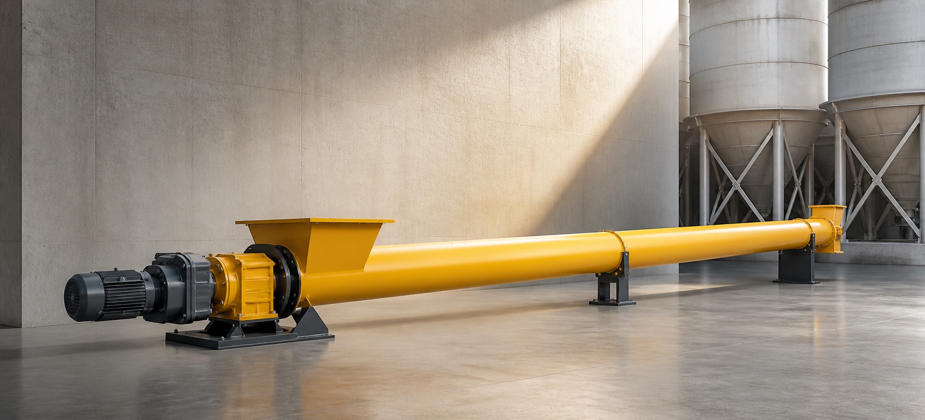
A cement screw conveyor installation succeeds when the structural supports, casing centerline, screw sections, bearings and drive are aligned as one machine. Do not use bolts, hanger brackets or the gearbox to pull a distorted assembly into place.
Use the approved general arrangement for VOGO’s project-configured cement screw conveyor. Catalog length and angle ranges do not replace foundation loads, support coordinates or interface drawings.
Verify the Site Before Assembly
Confirm foundation elevation, anchor locations, support steel, access, lifting plan, inlet and discharge coordinates, expansion joints, connected-equipment loads and power supply. Check that upstream and downstream flanges can meet without imposing pipe strain.
The casing support must carry the equipment and defined material load. A silo, weigh hopper or duct should not use the conveyor as an unplanned structural tie.
Establish the Centerline
The KWS engineering guide describes a string-line reference along the trough. A survey instrument may be preferable on long or elevated systems. The supplier drawing must state allowable horizontal and vertical deviation.
Recommended sequence:
- Set and temporarily secure supports.
- Place casing sections from the drive end in the documented order.
- Align section flanges and centerline before final tightening.
- Install screw sections, couplings and hanger supports without forcing.
- Set drive and end bearings on the common centerline.
- Stabilize the drive against visible movement.
- Verify inlet and discharge interfaces before final anchoring.
KWS’s installation guidance calls for hand rotation, seal adjustment, bearing lubrication, drive-oil verification, covers and safety labels before operation. Follow the exact equipment manual.
Check Hangers, Clearances and Rotation
A hanger should support the joint without lifting or bending adjacent screws. Measure flight-to-casing clearance at repeatable positions. Under verified isolation, rotate the complete screw by hand and listen or feel for periodic contact. Correct the alignment cause; do not grind an isolated rub without engineering approval.
Drive stability matters. KWS’s coupling-bolt fatigue guidance links drive movement and misalignment with cyclic coupling-bolt failure.
| Finding | Stop and check |
|---|---|
| Tight spot once per revolution | Bent section, eccentric coupling or misalignment |
| Continuous scrape | Centerline or casing distortion |
| Hanger pulled sideways | Support or coupling alignment |
| Drive visibly moves | Base, torque arm or structural support |
| Flange gap closes under bolts | Interface strain or fabrication error |
Pre-Commissioning Checklist
Verify fasteners, guards, covers, gaskets, seals, oil, grease, rotation arrow, motor data, VFD parameters, emergency stops, downstream-ready, zero-speed detection, overload settings and access platforms. Confirm that “enclosed” has not been converted into an unsupported airtight or pressure-rated claim.
Run empty first and record current, sound, vibration, bearing temperature, reducer temperature and leakage. Then introduce a controlled quantity of cement, not full upstream capacity. Increase load in agreed steps while monitoring discharge stability.
If the inlet is continuously covered by a silo, commissioning is feeder duty and must include head load and loaded restart. The startup torque guide provides that test basis. The hanger-bearing selection guide covers intermediate support material, journal and access decisions.
Safety Boundary
OSHA’s conveyor rule requires lockout or an otherwise inoperable and tagged condition during hazardous repairs. Alignment with guards removed is servicing. A control-circuit stop is not automatically energy isolation.
Control Interface Loads
The conveyor should connect to upstream and downstream equipment without being forced into position. A mislocated silo flange, rigid chute or support can introduce bending that changes flight clearance after bolts are tightened.
Before final connection, measure flange offset, angular mismatch and elevation. Use approved flexible or articulated connections only for the movement they are designed to accommodate; they are not substitutes for incorrect civil coordinates. Confirm that connected chutes do not transfer storage loads into the casing.
If the conveyor is inclined, verify the support reaction and restraint direction. A support that permits uncontrolled sliding can alter inlet and discharge alignment; an overconstrained arrangement can create thermal or assembly stress.
Verify Rotation Direction and Screw Hand
Motor direction, reducer output direction, screw hand and intended material direction must agree. Do not assume the electrical phase sequence is correct. Perform the first powered bump only after guards are installed, personnel are clear and the approved procedure permits it.
For a backstop-equipped drive, incorrect rotation can damage equipment. Check the reducer and backstop manual before energization. Mark the verified rotation on the drive and controls documentation.
Align the Drive Train
Measure coupling offset and angular alignment with an appropriate method. A flexible coupling accommodates limited movement; it does not authorize poor alignment. Check soft foot, base flatness, torque-arm position, bearing centers and fastener condition.
Recheck alignment after final anchoring and after connected chutes are tightened. Then recheck after the first loaded operating period because supports can settle. Record values rather than writing only “alignment OK.”
Cement Screw Conveyor Installation Hold Points
| Hold point | Evidence required | Release authority |
|---|---|---|
| Supports set | Survey coordinates and level | Site/structural team |
| Casing assembled | Centerline and flange record | Conveyor installer |
| Screw and hangers installed | Clearance and hand-rotation record | Mechanical supervisor |
| Drive aligned | Coupling and base measurements | Drive installer |
| Electrical complete | Rotation, insulation and protection checks | Electrical team |
| Ready for material | Empty-run baseline and interlock test | Commissioning lead |
Assigning release responsibility prevents later work from hiding an unresolved deviation.
Controlled Material Commissioning
Begin with a material rate below normal and a proven open discharge. Record mass rate, current, speed, temperatures, sound, vibration, seal leakage and support movement. Increase in planned steps only when the previous point is stable.
For inclined duty, watch fallback and retained material during stop. For control-fed duty, verify upstream feed stops on screw underspeed. For feeder duty, check head load, inlet drawdown and loaded restart without claiming the screw solves silo bridging.
If capacity is below target, verify actual density and speed before changing the drive. Installation misalignment, inlet restriction or downstream backpressure can imitate a sizing problem.
Turnover Package
Deliver approved drawings, survey and alignment records, lubricant list, torque/fastener records, VFD settings, interlock test, empty and loaded baselines, spare parts, maintenance access instructions and outstanding deviations. Photograph hidden interfaces before insulation or cladding.
A complete turnover package makes later troubleshooting faster and prevents field assumptions from becoming undocumented design changes.
Field Change Control
Do not drill new casing holes, trim flights, move hangers, change screw hand, add supports or modify torque arms without drawing approval. These changes can alter strength, alignment, clearance, material flow and drive loads.
Record every accepted deviation with dimensions, photographs, approver and as-built drawing revision. The maintenance team needs the actual installation, not only the original tender drawing, when diagnosing future wear or vibration.
Installation Tools and Evidence
Prepare calibrated survey, alignment, torque and electrical test equipment before assembly. Confirm lifting devices and temporary supports are rated for the actual sections. The method statement should show lifting points and prohibit loads on shafts, seals or guards.
Keep raw readings with the signed checklist. A photograph of a level or coupling is not a substitute for measured deviation, but it helps preserve location and orientation.
Conclusion
Cement screw conveyor installation should proceed from the support centerline outward. Align casing, screws, hangers, bearings and drive without forcing parts; verify clearances by isolated hand rotation; then commission empty and under controlled load. Record baseline current, temperature and vibration so later maintenance has evidence. Resolve site-interface strain before final acceptance.