
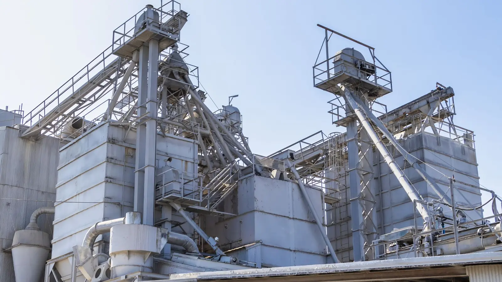
A cement screw conveyor inclination angle should be the lowest angle that satisfies the required vertical lift and available footprint. Raising the discharge saves floor space, but it also increases material fallback, reduces predictable volumetric efficiency, and adds gravity and upset-load demands to the drive. Do not apply a horizontal capacity figure to an inclined machine without recalculating and verifying the actual configuration.
VOGO’s project-configured tubular cement screw conveyors can be arranged for different lengths and angles, but the published range is only a selection boundary. The quotation and approved drawing must establish the material, inlet condition, centerline geometry, capacity, speed, drive, and restart case.
What Changes When a Cement Screw Conveyor Is Inclined?
In a horizontal control-fed conveyor, the screw advances a partially filled bed along the casing. When the casing is inclined, gravity creates a component opposite the conveying direction. Some cement can slip across the flight face or fall through the clearance between the flight tip and housing. The returning material occupies working volume and must be lifted again, so nominal displacement per revolution no longer equals delivered volume.
The KWS inclined screw conveyor guidance identifies angle, material characteristics, housing type, and screw pitch as interacting variables. It also separates inclined duty up to 45 degrees from vertical-conveyor design above that boundary. This is a useful classification, not permission to assume that every cement powder behaves acceptably at 45 degrees.
Bulk-material behavior remains decisive. Aerated cement can flood and surge; settled cement may compact and resist restart; moisture or agglomerates can change internal friction and fallback. The same angle can therefore produce different capacity and torque in commissioning than it did in a clean, free-flowing test material.
Cement Screw Conveyor Inclination Angle Decision Process
Use the following sequence before selecting diameter or motor power.
| Decision | Required input | Engineering consequence |
|---|---|---|
| Establish lift and run | Inlet elevation, discharge elevation, available centerline length | Defines the geometric angle and whether a lower angle is possible |
| Classify the inlet | Control-fed, intermittently covered, or continuously flood loaded | Determines conveyor versus feeder calculations |
| Define the cement condition | Bulk-density range, aeration, moisture, temperature, agglomerates, storage time | Establishes filling, fallback, and restart assumptions |
| Select conveying geometry | Tube or trough, screw diameter, pitch, clearance, speed | Determines usable volume and fallback control |
| Check the duty range | Minimum, normal, and peak mass flow | Prevents sizing only for one nominal point |
| Rate the drive | Running power, vertical lift, upset loading, start frequency, loaded restart | Sets motor, VFD, reducer, coupling, and shaft requirements |
| Confirm by evidence | Comparable material data or representative testing | Replaces an unsupported generic angle factor |
First calculate the angle from the actual centerline geometry:
Inclination angle, θ = arctan(vertical lift ÷ horizontal run)
This equation only describes the layout. It does not calculate capacity. If the plant can lengthen the horizontal run, reducing the angle may lower fallback and drive demand. That trade must include structural support, access, cleanout, and the position of upstream and downstream equipment.
Classify the Inlet Before Applying an Incline Factor
An inclined screw receiving a stable, limited stream from a rotary valve, weigh feeder, or other metering device is a control-fed conveyor. Its design can start with a conventional conveyor capacity method, followed by corrections and verification for the actual angle and material.
An inclined screw mounted directly under a hopper, bin, or silo with cement continuously covering its inlet is a screw feeder. The screw controls withdrawal while operating under material head. Its inlet geometry, increasing available capacity, torque, and drawdown pattern must be designed as a feeder. A horizontal or inclined control-fed capacity table cannot be transferred to that flooded section.
For the feeder boundary, see the separate cement silo discharge screw design guide. It covers increasing or variable pitch, tapered geometry, head load, silo flow behavior, and loaded restart without treating the screw as a cure for arching or rat-holing.
Why One Generic Capacity Correction Is Not Enough
The ANSI/CEMA 350-2021 publication is an accepted engineering reference covering screw-conveyor selection, material characteristics, capacity, components, safety, operation, and maintenance. It includes horizontal, inclined, vertical, and special configurations. A CEMA-based horizontal selection remains a useful baseline, but the inclined result still depends on application inputs.
Published rules of thumb often express inclined capacity as horizontal capacity multiplied by a single factor. That format hides the variables behind the factor: housing fill, flight pitch, speed, clearance, material friction, aeration, and inlet stability. Treat any factor as a preliminary estimate tied to its source conditions, not as a guaranteed cement throughput.
A peer-reviewed International Agrophysics study tested tubular augers at 0, 10, 20, and 30 degrees. Output and volumetric efficiency decreased as inclination increased, while power demand rose with inclination and speed. The tests used paddy grain, not cement, so their numerical results must not be copied into a cement proposal. Their value here is the experimentally supported direction of the effects and the finding that material properties change performance.
The Oklahoma State University Extension auger guide likewise reports that elevation angle reduces capacity and changes power demand. Its tables concern agricultural materials and small augers. They reinforce the need for material-specific verification rather than providing cement ratings.
Worked Layout and Capacity Scenario
Assume a control-fed cement conveyor must provide 4.0 m of vertical lift. Two layouts are possible:
- Layout A has an 8.0 m horizontal run.
- Layout B has a 5.0 m horizontal run.
The geometric angles are:
- Layout A: arctan(4.0 ÷ 8.0) = 26.6°
- Layout B: arctan(4.0 ÷ 5.0) = 38.7°
Both layouts reach the same elevation, but Layout B is not simply a shorter version of Layout A. Its steeper angle increases the risk of fallback, may require different pitch or speed, and can raise the temporary load after an interrupted flow. The engineer should not select Layout B using the same diameter, RPM, and horizontal capacity assumption without a new performance and torque check.
Suppose the process requires 18 t/h and the verified operating bulk density is 1.20 t/m³. The required delivered volumetric rate is:
18 t/h ÷ 1.20 t/m³ = 15.0 m³/h
This is a project example, not VOGO performance data. The next step is to select a horizontal control-fed baseline using the screw conveyor capacity calculation method, then verify that the proposed inclined geometry delivers at least 15.0 m³/h across the actual density and condition range. Do not multiply by an unsourced factor and declare the result final.
Housing, Pitch, Speed, and Diameter Trade-Offs
A tubular housing limits the open space over the flights through which material can fall back. That can improve inclined conveying compared with an open U-trough, but “tubular” does not mean airtight or pressure-rated. Shaft seals, flanges, covers, vents, and connected equipment still define the containment boundary.
Shorter pitch can reduce the distance available for backward slip and is commonly considered for inclined service. It also changes displacement per revolution and can alter filling and power. A larger diameter provides more working area at a given speed, but it does not remove the need to verify inlet loading, clearance, torque, and structural support.
Increasing speed may recover some output, but it is not an unlimited correction. The peer-reviewed auger tests found that output reached an application-dependent maximum and then declined at higher speed, while power continued to increase. For cement, higher speed can also affect wear, bearing temperature, dust behavior, and material agitation. Use supplier calculations and representative evidence instead of treating RPM as a universal remedy.
Drive and Upset-Load Checks
The drive must do more than lift the normal mass flow. Check at least these cases:
- Empty mechanical running resistance.
- Normal conveying at minimum and maximum credible bulk density.
- Gravity lift at the required mass flow.
- Material fallback after a downstream stop or interrupted discharge.
- Restart with material settled in the lower section.
- A downstream restriction up to the defined overload trip point.
Document screw-shaft torque for running, loaded restart, and protection settings. Verify motor and VFD low-speed torque, motor cooling, reducer output torque and service factor, coupling and shaft limits, starts per hour, and zero-speed or high-current protection. The control sequence should prove the downstream path ready before starting and stop upstream feed on a conveyor trip.
Inclined Conveyor Specification Checklist
Send the supplier the following information:
- material name and minimum, normal, and maximum bulk density;
- aerated and settled condition, moisture, temperature, abrasiveness, and agglomerate size;
- minimum, normal, and peak mass-flow requirements;
- confirmation of control-fed conveyor or flood-loaded feeder duty;
- inlet and discharge centerline coordinates, vertical lift, horizontal run, and angle;
- available envelope, support points, maintenance access, and cleanout method;
- preferred housing, screw pitch, and speed range, if already constrained;
- start frequency, loaded-restart requirement, power supply, and VFD range;
- upstream/downstream interlocks and overload or zero-speed protection;
- operating pressure direction, venting, leakage requirement, seals, and flange details.
The broader screw conveyor quotation input checklist explains how to package the material, process, layout, electrical, and documentation inputs without repeating the inclined-design decisions above.
Conclusion
The correct cement screw conveyor inclination angle is the lowest practical angle supported by the plant layout and verified conveying performance. Calculate the geometry, distinguish control-fed conveyor duty from flood-loaded feeder duty, convert mass flow to a density-based volumetric requirement, and then verify fallback, pitch, speed, diameter, power, and loaded restart. Horizontal capacity and generic incline factors are screening tools, not guarantees. Send the layout coordinates, cement condition, flow range, and restart duty for a project-specific selection.