
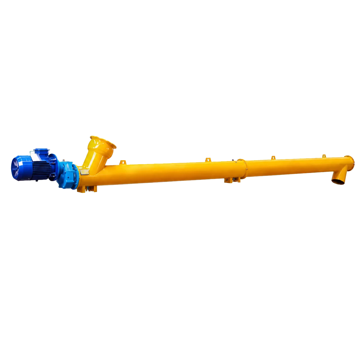
Continuous plant operation in the cement, dry-mix mortar, and asphalt industries requires the reliable transfer of powdered materials. Tubular screw conveyors are the standard for enclosed powder conveying because of their compact footprint and dust containment. Modern screw conveyors evolved from the Archimedes screw and move granular and powdered materials over short and medium distances.
Selecting the correct size and configuration requires careful engineering. An incorrectly sized conveyor causes material blockages, high energy consumption, premature wear, and missed throughput targets. This guide covers cement screw conveyor sizing, including the calculations and design factors mechanical engineers and procurement managers need to specify the correct equipment.
Understanding material properties and filling coefficients
Screw conveyor calculations depend on the physical characteristics of the material. For cement, fly ash, and mineral fillers, parameters include bulk density, moisture content, particle size, temperature, and abrasiveness. These properties determine the filling coefficient (φ), which is the fraction of the trough cross-section filled with material during operation. Free-flowing, non-abrasive powders can be conveyed at higher filling levels, between 0.40 and 0.45. Abrasive, cohesive, or aerated materials require lower filling levels, between 0.25 and 0.35, to reduce friction and prevent compaction, which limits wear on the helical flight and tubular casing. Defining these material traits prevents undersized or overloaded equipment. The application also determines if the system needs continuous conveying or controlled feeding (metering), which dictates the operational speed and drive precision.
Capacity calculation formula
After determining material properties, calculate the theoretical capacity. Engineering standards such as ANSI/CEMA Standard No. 350 and GB/T 10595-2009 define the standard capacity formula for a horizontal screw conveyor:
Q = (π/4) × D² × P × n × ρ × φ × 60
Where:
- Q = Capacity (tonnes per hour, t/h)
- D = Screw outside diameter (metres)
- P = Pitch of the screw helix (metres). For standard pitch designs, P is typically equal to D.
- n = Rotational speed (revolutions per minute, RPM)
- ρ = Bulk density of the material (tonnes per cubic metre, t/m³)
- φ = Filling coefficient (dimensionless)
The equation shows that capacity is highly sensitive to screw diameter because the diameter is squared. A small increase in diameter increases volumetric throughput. Manufacturers offer a range of selection diameters (Ø89, Ø114, Ø168, Ø219, Ø273, Ø323, and Ø407 mm) to meet project requirements without using excessive rotational speeds, which cause material degradation and wear.
Adjusting for inclination and conveying distance
The basic capacity formula assumes a horizontal installation. Engineers often install conveyors at an incline to transfer materials between process stages, such as moving cement from a storage silo to a weighing hopper in a concrete batching plant. As the inclination angle increases, effective capacity decreases because gravity pulls the material against the direction of the helical flight. Designers must apply an inclination correction factor to the theoretical capacity. A 15-degree incline reduces capacity to 87 per cent of the horizontal value, and steeper angles require greater derating.
Centreline length also affects the mechanical design. Longer conveyors require intermediate hanger bearings to support the central shaft and prevent sagging. Engineers must plan the bearing placement, inlet, and outlet layout to maintain material flow and the structural integrity of the rigid tubular body.
Power calculation and drive selection
Sizing the conveyor geometry is one part of the design; selecting the correct drive motor is the other. The required shaft power depends on the material mass, total conveying distance, inclination angle, and system friction characteristics. A standard power calculation uses the material volume, conveying distance, and total drive system efficiency. Designers usually add a safety factor for start-up torque and material compaction. Standard configurations use 3-phase motors (e.g., 380 V, 50 Hz, 4-pole, 1,450 rpm). The specific power supply, start frequency, and process temperature dictate the final drive configuration. Selecting the correct motor prevents overloading during start-up.
Conclusion
Selecting a cement screw conveyor requires calculating bulk density, filling coefficients, inclination angles, and power requirements to design an enclosed powder conveying system. Published capacity ranges are selection references, not guaranteed outputs. Actual capacity and power depend on the conveyed material, filling degree, inclination, and operating conditions, and must be confirmed for each project. VOGO Machine supplies tubular screw conveyors for conveying and controlled feeding duties, with selection diameters from Ø89 mm to Ø407 mm and lengths from below 1 m to below 15 m. Visit the VOGO cement screw conveyor product page for technical specifications, selection parameters, and datasheets.