
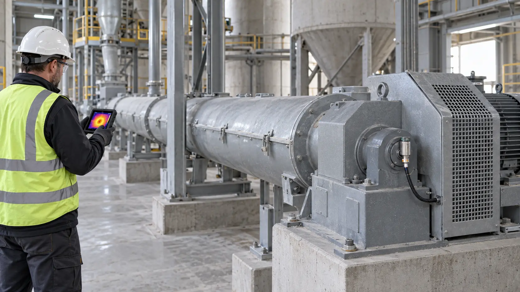
Cement screw conveyor bearing temperature monitoring should detect a meaningful change from a repeatable baseline, not compare every bearing with one generic temperature limit. Define the bearing, sensing point, operating state, ambient condition, lubricant condition, alarm action, and proof test before commissioning. A rising trend is a prompt to diagnose; temperature alone does not name the fault.
On a project-configured cement screw conveyor, end-bearing arrangement, reducer, speed, duty, seals, and instrumentation depend on the approved design. VOGO’s public product information does not claim a supplied temperature sensor, alarm threshold, bearing temperature rating, or safety integrity level. Those items belong in the project specification and vendor submittals.
Define what the sensor is actually measuring
Start with a tagged measurement map. A drive-end rolling bearing, tail-end bearing, gearbox bearing, motor bearing, and internal hanger bearing do not have the same construction or thermal path. Some intermediate supports use plain bushes rather than rolling bearings. The hanger-bearing selection guide explains that separate component boundary.
A bolted surface sensor reads the housing through a contact interface. A probe installed in a prepared housing port can sit nearer the bearing or lubricant. An infrared survey reads a visible surface and is sensitive to target emissivity, angle, distance, contamination, and line of sight. These methods can all be useful, but their readings are not interchangeable. When changing sensor type or location, establish a new baseline rather than splicing unlike values into the old trend.
ISO 17359:2018 gives general procedures for setting up a machine condition-monitoring program. Applied here, that means documenting the failure modes, measurement technique, data collection, assessment criteria, response, and review process. The standard does not supply a universal screw-conveyor temperature limit.
For a permanent device, follow the bearing, housing, and sensor manufacturers’ installation instructions. The 4B ADB Lug documentation, for example, describes surface-mounted NTC, PT100, and 4–20 mA versions intended to bolt to a bearing housing or machine casing. That proves the distinction between sensor outputs and mounting styles; it is not a recommendation that one product fits every conveyor or hazardous area.
Set up cement screw conveyor bearing temperature monitoring
Create the baseline after mechanical alignment, lubrication, guarding, direction checks, and instrument-loop verification are complete. Measure long enough for the thermal trend to approach a stable operating region. Record at least:
- equipment and bearing tag, sensor type, exact location, insertion depth or surface preparation;
- ambient temperature near the bearing and, when relevant, conveyed-material temperature;
- shaft speed, material rate, trough loading, incline, and direction;
- elapsed time from start, run duration, and stop/start history;
- lubricant identity, amount, method, and elapsed time since relubrication;
- motor current, vibration observation, zero-speed status, and unusual sound or leakage.
Collect separate empty and representative loaded runs. A control-fed conveyor receives a metered upstream flow. A screw continuously flood-loaded beneath a hopper, bin, or silo is a screw feeder; its head load and loaded-start behavior require a distinct baseline and drive review. Do not apply a control-fed conveyor trend or capacity table to feeder duty.
The SKF Bearing Damage and Failure Analysis guide states that operating temperature should be monitored at bearing positions and that an increase under unchanged conditions can indicate impending damage. It also warns that grease-lubricated bearings may show a natural temperature rise for one or two days after initial startup or relubrication. Therefore, annotate grease events and avoid treating every post-grease rise as damage—or dismissing a sustained rise without inspection.
Work a temperature-rise trend example
The following calculation is an illustrative comparison, not an alarm or shutdown recommendation.
During an accepted loaded baseline, the drive-end housing stabilizes at 52 °C while local ambient is 28 °C:
Baseline temperature rise = 52 - 28 = 24 K
At the same speed and nominal material rate one month later, the housing reaches 67 °C while ambient is 31 °C:
Current temperature rise = 67 - 31 = 36 K
Increase in temperature rise = 36 - 24 = 12 K
The rise above ambient has increased by 50 percent in this example. That change warrants a controlled response, but it does not identify the cause. First verify that the sensor, load, run time, lubrication state, and ambient reference are comparable. Then examine motor current and vibration trends. A simultaneous rise in current may point toward added mechanical or material load; stable current with local heating may focus attention on the bearing, fit, seal, or lubricant. The motor-current monitoring guide and vibration troubleshooting guide provide those corroborating methods.
Project alarm values must remain within the lowest applicable limit from the bearing, grease, seal, sensor, cable, housing, ambient classification, and adjacent equipment, with engineering margin and a defined response time. A permitted absolute temperature does not make a rapid unexplained rise acceptable. Conversely, a single handheld reading above a historical value is not enough to trip production without confirming the measurement and required protective action.
Diagnose a hot bearing without guessing
Use the pattern and timing to narrow the inspection plan. Keep the conveyor guarded while gathering external readings; isolate it before physical inspection.
| Observed pattern | Verify first | Plausible causes to investigate |
|---|---|---|
| Rise begins soon after greasing | Grease type, quantity, route, event time | Normal churning period, overfill, blocked relief path, incompatible grease |
| One end bearing rises; load is steady | Sensor attachment and paired-bearing trend | Local lubrication loss, contamination, fit, seal drag, alignment, bearing damage |
| Both end bearings and motor current rise | Material rate, buildup, discharge, speed | Higher loading, restriction, rubbing, misalignment, process upset |
| Temperature rises with vibration | Measurement locations and speed orders | Looseness, alignment error, bearing degradation, rotating contact |
| Temperature jumps without physical corroboration | Loop signal, terminals, scaling, open/short diagnostics | Sensor or wiring fault, loose surface contact, PLC scaling error |
| Repeated rise after loaded restart | Restart state and torque history | Settled material, feeder head load, inadequate drive margin, mechanical restriction |
Schaeffler’s rolling-bearing technical principles link contamination, seating geometry, alignment, lubrication quantity, seal friction, and temperature behavior. This is why a hot-bearing response should preserve evidence before adding grease, loosening a seal, or changing alignment. An unplanned adjustment can hide the initiating condition and create another fault.
Do not assume a hot end bearing proves the screw is blocked. Inspect the system boundary: discharge restriction, flight-to-casing contact, coupling alignment, support movement, seal condition, bearing fit, foundation, material buildup, and upstream feed. A screw conveyor does not independently cure silo arching, rat-holing, or bridging; silo geometry, outlet size, moisture, consolidation, aeration, and flow aids remain separate system factors.
Design alarm, stop, and proof-test behavior
Define the response in a cause-and-effect document. A warning may call for confirmation and controlled process reduction. A higher protective threshold may stop upstream feed first and then stop the screw according to the approved sequence. For a flood-loaded screw feeder, an immediate stop can leave a full machine under head load, so the restart case, VFD low-speed torque, reducer service factor, and stall protection must already be engineered.
Specify delay, hysteresis, latching, reset authority, signal-fault response, and restart permissives. Delay should reject proven transient behavior without masking a real heating rate. If an open or short circuit must initiate a safe response, verify that behavior instead of assuming the input module is fail-safe. The 4B T400N documentation is one manufacturer example of separate alarm and stop relays, circuit-fault detection, and a test function; the required architecture still comes from the project’s risk assessment.
Proof-test the full loop at commissioning and at the documented interval: sensor or approved simulator, field wiring, input scaling, alarm, stop output, upstream isolation, event record, reset, and restart prevention. Record the test value and uncertainty. A PLC screen that changes color proves only part of the chain.
Commission with a practical acceptance checklist
- Match every bearing and sensor tag to the approved drawings and data sheets.
- Confirm the sensor location, mechanical attachment, cable protection, grounding, and hazardous-area suitability where applicable.
- Verify transmitter range, engineering units, PLC scaling, channel-fault detection, and historian timestamp.
- Record empty and loaded thermal trends with ambient, speed, rate, run time, current, vibration, and lubrication state.
- Obtain approved warning and shutdown criteria with their technical basis; reject unexplained generic limits.
- Simulate warning, shutdown, sensor fault, reset, and restart behavior without exposing personnel to moving parts.
- Check that upstream feed stops in the intended sequence and that a loaded restart remains within the approved drive duty.
- Store the baseline plot, proof-test results, alarm setpoints, change authority, and next test date in the maintenance record.
The enclosure around the screw may reduce ordinary dust escape, but enclosed does not mean airtight or pressure-rated. Pressure, purge air, leakage, and dust ingress can influence seals and bearing conditions; assess them from the actual design. Do not drill a sensor port into a bearing housing or conveying enclosure without manufacturer approval and a contamination, strength, and sealing review.
Keep the safety boundary explicit
Temperature monitoring is a condition and protection function, not permission to approach rotating equipment. Keep couplings and shafts guarded, use external measurement points, and follow the site’s machinery-safety arrangements. HSE machinery guidance emphasizes suitable guards and safe isolation before maintenance.
Before touching a housing, removing a guard, opening a cover, clearing material, or inspecting a bearing, stop and isolate all hazardous energy under the site procedure. Verify electrical isolation, motion cessation, stored mechanical energy, upstream material, silo head, pneumatic pressure, and hot surfaces. A stopped command, emergency stop, temperature alarm, VFD inhibit, or process zero-speed indication is not by itself hazardous-energy isolation.
Conclusion
Cement screw conveyor bearing temperature monitoring is credible when each sensor has a defined thermal path, each trend compares like operating states, and every alarm leads to a tested response. Establish empty and loaded baselines, annotate relubrication, compare temperature rise as well as absolute value, and corroborate changes with current, vibration, process, and inspection evidence. Set project limits from actual component data and risk, never from a universal internet number.
For a monitoring review, send VOGO the conveyor drawing, bearing and lubricant data, operating cases, sensor specification, baseline records, and required alarm/stop sequence.