
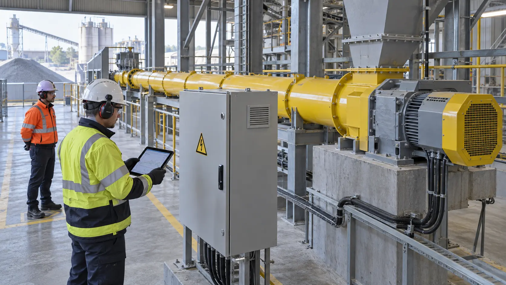
Cement screw conveyor motor current monitoring works best as a comparison tool: define the measurement point and operating state, establish empty and loaded baselines, then act on sustained deviation. Do not copy one percentage of nameplate current into every project. Motor, starter or VFD data, duty, ambient conditions, applicable electrical rules, and process consequences determine the protective settings.
The VOGO cement screw conveyor range is configured for each project’s material, route, drive, and interfaces. Published product information does not state a universal normal current, alarm threshold, trip delay, or restart allowance. Those values belong in the approved motor and control documentation for the supplied machine.
Separate indication, alarm, and protection
Three functions are often confused. A current display tells the operator what the selected device measures. A process alarm warns that load has moved outside an agreed operating band and may initiate a controlled feed reduction or stop. Motor overload protection prevents unacceptable thermal stress according to its design and settings. One device may support more than one function, but the engineering records must still identify each function, its measurement source, priority, delay, action, and reset rule.
IEC 60947-4-1:2023 covers electromechanical contactors and starters, including motor protective switching devices, within its stated voltage scope. It includes methods of motor overload protection; it does not provide a cement-conveyor current threshold. Use the applicable edition and the protective-device manufacturer’s instructions when selecting current range, trip class or protection model, short-circuit coordination, and reset behavior.
Electronic relays can expose current, thermal utilization, phase loss or imbalance, time-to-trip, and trip history. The Rockwell E300 manual and ABB M10x manual show why settings are device-specific. Their features and parameter names are not evidence that a VOGO conveyor includes either device.
Keep these statements distinct:
| Statement | Meaning | Acceptance source |
|---|---|---|
| Verifiable fact | The installed motor nameplate current is 32 A | Motor nameplate and approved data sheet |
| Project decision | Warn after current exceeds an approved limit for a stated delay | Cause-and-effect chart and risk review |
| Supplier information | A quoted drive or relay provides specified current data | Approved order submittal for that project |
Choose the correct measurement point
For a direct-on-line motor, a properly installed relay or three-phase current transducer may provide the signal. For a VFD-fed motor, distinguish mains input current from motor-side output current and the drive’s calculated torque or load value. They are produced at different points by different methods and must not be substituted without the drive manual and commissioning evidence.
Document at least:
- motor rated voltage, current, power, frequency, duty and connection;
- starter, overload relay or VFD make, model, firmware, current range and relevant settings;
- current source, engineering units, phase treatment, scaling, sampling interval and filtering;
- screw speed or VFD output frequency, rotation direction and reducer ratio;
- material, measured bulk density where used, feed rate, inlet condition and downstream state;
- ambient and motor temperature state, run duration, and alarm or trip status.
A single-phase reading can hide imbalance. Use the protective device’s approved method and record all relevant phase values or its validated aggregate value. First check instrument scaling and wiring when a displayed value conflicts with a calibrated meter or with other drive data.
Build empty and loaded current baselines
Collect an empty baseline after alignment, lubrication, direction, guards, and mechanical clearance have passed inspection. Run at each normal speed long enough for the reading to stabilize. Record minimum, typical, maximum, phase values, and any periodic fluctuation. A high or unstable empty current points toward electrical supply, brake, coupling, alignment, bearing, seal, rubbing, or measurement problems before cement is introduced.
Then collect loaded data at defined minimum, normal, and maximum process rates. Hold material condition, screw speed, inlet control, and downstream route stable. Repeat each point rather than accepting one snapshot. Link the records to the installation and alignment hold points and use the vibration troubleshooting method when mechanical load and vibration rise together.
Do not treat low current as proof of good conveying. Starved feed, a broken coupling, detached flight, incorrect rotation, slipping drive, or empty inlet can reduce current while capacity fails. Confirm actual rotation and flow independently; the zero-speed switch setup guide explains shaft-level motion proof.
Illustrative baseline calculation
Assume a project has a 32 A motor nameplate value. Three stable commissioning runs at the defined normal duty produce phase-maximum currents of 21.8, 22.4, and 22.1 A:
Mean normal-duty current = (21.8 + 22.4 + 22.1) / 3 = 22.1 A
Observed load ratio = 22.1 / 32 = 0.691, or 69.1% of nameplate current
If a later comparable run records 27.6 A, the change from baseline is:
Current increase = (27.6 - 22.1) / 22.1 × 100 = 24.9%
That 24.9% increase is a diagnostic trigger in this example, not a proposed universal alarm and not proof of overload. Review voltage, speed, feed rate, material condition, pressure, temperature, phase values, and mechanical observations before assigning a cause. The 32 A nameplate value also does not by itself define the correct relay setting or trip time.
Set cement screw conveyor motor current monitoring logic
Develop alarm logic from captured traces of normal starts, stable running, planned rate changes, and controlled stops. Starting current and acceleration time can be very different from steady state, so a warning needs a state-dependent delay or inhibition that does not defeat the independent motor protection.
A practical cause-and-effect sequence can include:
- Advisory deviation: flag a sustained change from a comparable baseline for maintenance review without stopping the process.
- High-load warning: alert the operator, retain the trend, and prevent an upstream rate increase.
- High-high process action: stop or reduce upstream feed, keep the downstream path available where safe, and stop the screw through the approved sequence.
- Protective trip: let the engineered overload device act according to its thermal model and settings; latch the event and preserve first-out data.
- Manual reset: require confirmation that the cause is removed and the machine is safe before re-enabling a start.
Do not use PLC filtering to mask a genuine protective trip. Conversely, do not make a fast process alarm so sensitive that every normal acceleration causes nuisance shutdown. Test the complete path by an approved simulation or controlled load method; forcing current beyond a safe limit is not required to prove logic.
Diagnose high current without guessing
Use the time pattern and corroborating evidence to narrow the cause. Stop immediately for impact, rubbing, smoke, rapid temperature rise, repeated protective trips, structural movement, or any unsafe condition.
| Current pattern | Checks after a safe stop or from approved external measurements | Possible causes, not conclusions |
|---|---|---|
| High before material enters | Supply, brake release, alignment, bearings, seals, rotor direction, scaling | Electrical fault, drag, rubbing, instrument error |
| Rises with rate and falls when feed stops | Feed rate, bulk condition, fill, outlet restriction | Normal load response, excessive fill, downstream restriction |
| Periodic fluctuation | Screw-speed order, vibration, casing contact, eccentricity | Bent shaft, misalignment, flight contact, periodic feed |
| One phase differs materially | Voltage, terminals, current sensors, motor and relay diagnostics | Phase imbalance, connection fault, sensor fault |
| Sudden rise with falling speed | Speed proof, outlet, material state, torque indication | Jam, fallback, seized support, drive problem |
| Normal current but low capacity | Actual shaft rotation, feed availability, direction, leakage path | Starvation, slip, broken component, wrong rotation |
Trend current with screw speed, not only clock time. At reduced VFD speed, cooling, available torque, drive control mode, and material behavior change; the same amp reading may represent a different duty. Retain first-out events so a zero-speed trip, downstream fault, high current, and upstream stop are not misread in reverse order.
Preserve the feeder and system boundaries
A screw with inflow controlled by an upstream valve or separate feeder is a control-fed conveyor. A continuously open hopper, bin, or silo over the inlet flood-loads the screw, making it a screw feeder. The feeder case needs head-load, withdrawal, full-start torque, VFD low-speed torque, reducer service factor, and stall-protection checks. A normal conveyor current baseline cannot validate flood-loaded feeder design.
Feeder inlet geometry may use increasing pitch, tapered outside diameter, or a designed mass-flow arrangement. Reduced pitch alone is not a complete solution. Nor can current monitoring prove that the silo is free from arching, rat-holing, or bridging; outlet geometry, wall friction, consolidation, moisture, compaction, aeration, and flow aids remain system variables.
Enclosed also does not mean airtight or pressure-rated. Dust extraction, positive or negative pressure, seal purge, and connected flexible elements can change mechanical load or leakage. Record their operating state during baseline tests and verify any pressure rating from the complete design.
Commission, test, and hand over the function
The commissioning record should contain the approved setpoints, time delays, state-dependent logic, scaling checks, empty and loaded traces, simulated cause-and-effect results, protective-device report, first-out sequence, reset test, software revision, parameter backup, and authorized sign-off. Re-test affected paths after any motor, reducer, VFD, relay, PLC, screw, bearing, seal, or process change.
OSHA 1918.64 requires powered conveyors within its scope to operate with overload devices, guards, and safety devices in place and operable; it also requires lockout/tagout before removing the cause of a jam or overload. For general hazardous-energy principles, OSHA’s lockout/tagout overview describes why machinery must be disabled against unexpected energy release during service.
Treat those sources according to the workplace and jurisdiction to which they apply. Regardless of location, a current alarm, stop command, emergency stop, VFD inhibit, or tripped overload is not proof of zero hazardous energy. Follow the site-specific isolation procedure before opening a cover, touching the drive, clearing material, or attempting repair. Repeated reset or reverse jogging is not a diagnostic method.
Conclusion
Cement screw conveyor motor current monitoring is useful when each value belongs to a known measurement point, speed, material duty, inlet condition, and process state. Establish repeatable empty and loaded baselines, use current deviation as a diagnostic clue, keep the process warning separate from engineered overload protection, and preserve first-out evidence. Confirm motion and capacity independently, maintain the feeder/conveyor distinction, and isolate hazardous energy before investigating a jam or overload.
For a project monitoring review, send VOGO the motor and drive data, screw speed range, inlet condition, duty points, current traces, cause-and-effect chart, and required protective standard.