
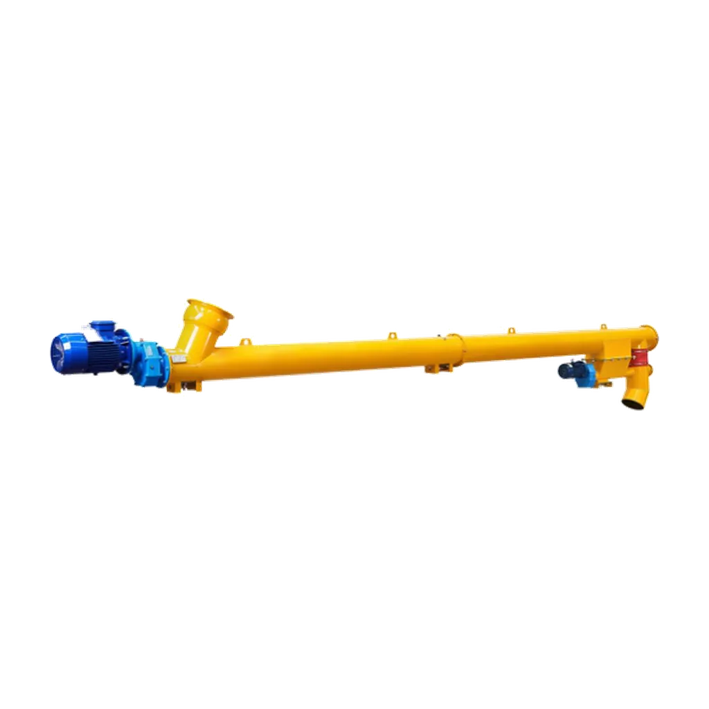
The mechanical integrity of a screw conveyor depends on its shaft design. In cement and bulk material handling, the shaft transmits driving torque to the flights and supports the weight of the rotating assembly and conveyed material. Inadequate shaft design causes excessive deflection, which leads to flight-to-trough contact, accelerated wear, and structural failure. Mechanical design engineers and maintenance managers use calculations for shaft deflection, critical speed, and cross-section selection to optimise lifecycle costs. Screw conveyor shaft design requires mitigating resonance, managing unsupported spans, and selecting the appropriate shaft type for specific torque and weight constraints. Applying these calculations and engineering standards reduces shaft failures and maintains continuous operation. Procurement professionals apply these principles to specify equipment for new installations and upgrades.
Managing shaft deflection limits
Shaft deflection limits the maximum span of screw conveyors. When a shaft bends under the combined weight of the shaft, flights, and material, the clearance between the flight edge and the trough decreases. If deflection exceeds acceptable limits, the flights rub against the trough. This causes abrasive wear and increases power requirements. Beam theory provides the formula to calculate the maximum deflection of a simply supported shaft under a uniformly distributed load. The calculation requires the distributed load per unit length, the unsupported span length, the modulus of elasticity of the shaft material, and the area moment of inertia.
Deflection increases with the fourth power of the unsupported length, so a small increase in span causes a large increase in shaft bending. The distributed load includes the weight of the shaft, the flights, and the effective weight of the material in the trough. Reducing the unsupported span controls deflection, typically by adding intermediate hanger bearings. Each hanger bearing creates a potential point for material hang-up and requires regular maintenance. Designers must balance minimising deflection through larger shaft diameters or stiffer materials with limiting the number of intermediate supports to maintain material flow and reduce maintenance intervals.
Critical speed and resonance avoidance
Deflection governs the static and quasi-static structural limits of the shaft, while critical speed controls its dynamic stability. Critical speed is the rotational frequency at which the shaft’s natural frequency is excited and causes resonance. Operating a screw conveyor at or near this speed produces severe vibrations. These vibrations can quickly destroy hanger bearings, misalign the drive train, and cause fatigue failures in the shaft.
Calculating the critical speed requires analysing the shaft diameter, material density, modulus of elasticity, and the mass of the attached flights. A standard engineering rule of thumb is to set the operating speed at least 20 percent below the first critical speed. Alternatively, the operating speed can be set above 1.2 times the critical speed, but the first method is much more common in screw conveyors. The risk of encountering critical speed increases for long conveyors operating at higher speeds. Engineers must evaluate the combined mass of the shaft and the flights, as the flights add rotational inertia. If the calculated operating speed approaches the critical threshold, designers must increase the shaft diameter to raise the natural frequency. They can also reduce the operating speed by adjusting the drive ratio, provided the required volumetric capacity is still met.
Solid shaft versus pipe shaft selection
Selecting a solid or pipe (hollow) shaft depends on torque requirements, weight limits, and span lengths. Solid shafts are used in short conveyors or heavy-duty applications that require high torsional strength. They resist bending well and are easier to manufacture and machine for flight attachment. As conveyor length increases, however, the solid shaft weight becomes a large part of the total load. This increases deflection and requires more power to turn the conveyor empty.
Pipe shafts have a higher strength-to-weight ratio. Removing material from the centre of the cross-section, where it contributes least to the moment of inertia, reduces the shaft weight without sacrificing torsional rigidity or bending resistance. This lower weight reduces the distributed load, which minimises deflection and allows for longer unsupported spans or fewer hanger bearings. Engineers prefer pipe shafts in long cement conveyors to minimise empty running torque and reduce structural load. Selection depends on the transmitted torque, allowable deflection limits, and the economic trade-off between the higher material cost of a large-diameter pipe and the savings in drive power and bearing maintenance.
Optimising lifecycle costs and maintenance
A well-designed shaft prevents immediate mechanical failure and reduces total lifecycle costs. Broken shafts and premature bearing failures often result from design compromises, such as inadequate deflection margins or ignored critical speed thresholds. Applying shaft design calculations and selecting the correct cross-section minimises unplanned downtime.
Standardised components and project-specific configurations match the shaft and its supports to the actual duty. Specifying the correct hanger bearing type and spacing based on deflection calculations prevents uneven wear and extends the service life of the bearings and flights. Regular inspection protocols should include checking shaft alignment, measuring flight clearance, and monitoring hanger bearing temperatures. Conveyors designed with adequate safety factors and clear deflection margins reduce the frequency of emergency interventions. Correct shaft design and maintenance make the screw conveyor a reliable component of the material handling system.
Conclusion
Screw conveyor shaft design requires balancing static deflection limits, dynamic critical speed thresholds, and cross-sectional selection. Engineers calculate distributed loads, manage unsupported spans, and choose between solid and pipe shafts based on torque and weight constraints to maintain continuous operation. These principles minimise wear, prevent resonance, and lower lifecycle costs in cement and bulk material handling systems. VOGO Machine manufactures cement screw conveyors with durable construction and project-specific configurations, available in diameters from 89 mm to 407 mm. For selection parameters or to download the datasheet, visit the cement screw conveyor product page.