Air slide conveyor commissioning should prove three things with the actual product: the powder fluidizes, gravity carries it through the complete route, and displaced air leaves through a controlled filtered path. A blower running and powder appearing at the outlet are not enough. Record feed rate, conveying rate, section pressure and visible conditions so later troubleshooting has a baseline.
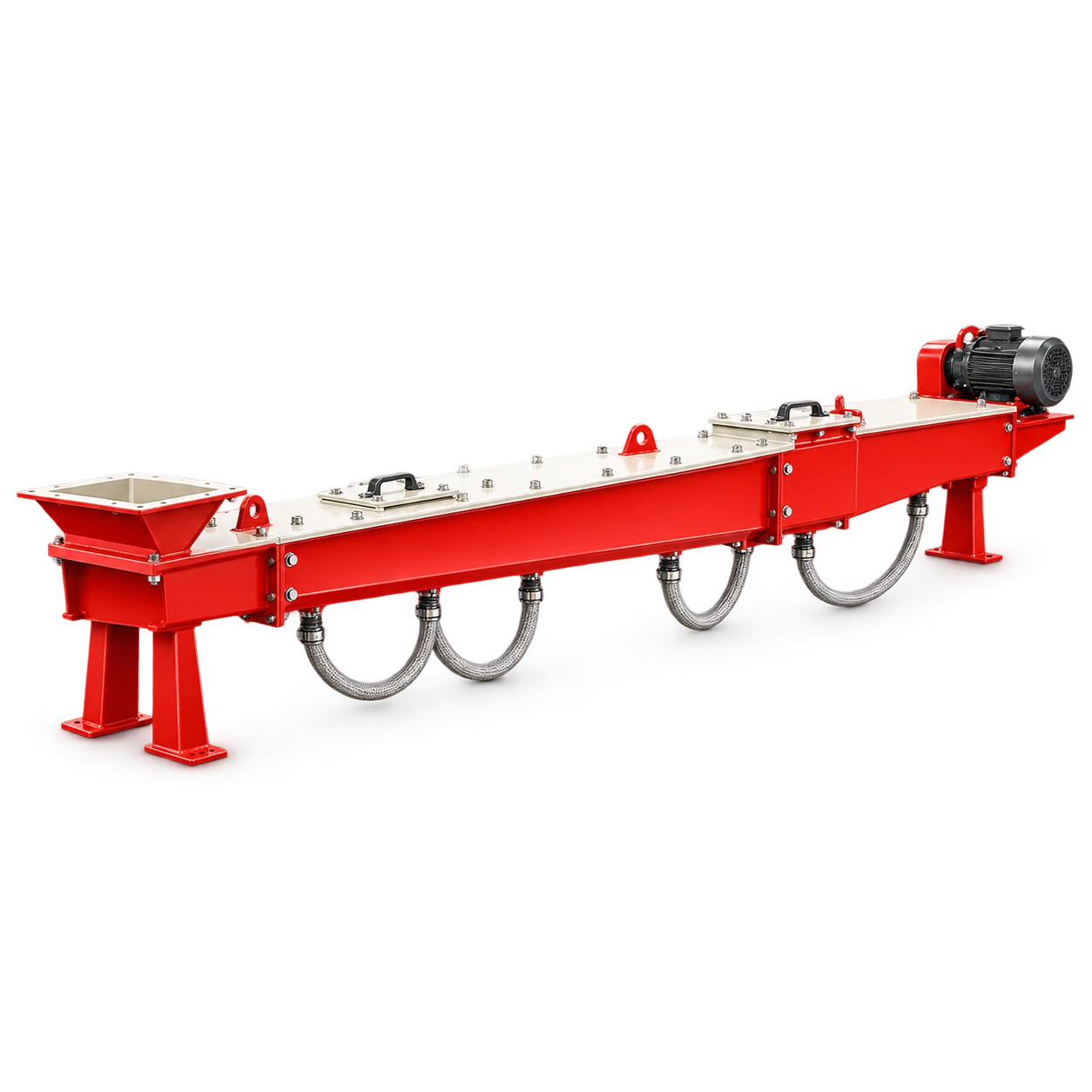
The VOGO Air Slide Conveyor is an enclosed pneumatic chute range with no moving conveying parts. The catalog lists five standard widths and directs selection by conveying rate, chute width, air pressure and route length. It does not publish a universal slope, air pressure or capacity for every powder, so those values must be confirmed from the material and project duty.
Understand the air-gravity boundary
An air slide has an upper material chamber and a lower air chamber separated by porous media. Low-pressure air passes upward through the media and reduces friction between fine particles. Gravity then moves the aerated powder down a continuously falling route.
Fuller Technologies describes its Airslide gravity conveyor as an upper and lower trough separated by fabric, with the lower trough supplied by low-pressure fluidizing air. Vortex gives the same functional boundary in its Aero-Slide engineering description: the blower supplies the lower chamber, air passes through the porous media, and excess air is vented through a bin or filter.
This is not the same as dilute-phase pneumatic conveying. The conveying air does not propel product through a pressurized pipeline, and the chute cannot lift material uphill. An enclosed casing is not automatically airtight, pressure rated or suitable for combustible dust. Those properties require project-specific documentation for the complete system.
Before commissioning, record:
- material identity, particle-size distribution, bulk density and temperature;
- moisture limit and any tendency to absorb water, cake or set;
- required mass or volumetric rate and expected turndown;
- chute width, total length, branch points and elevation profile;
- blower, filter, inlet and discharge equipment data;
- the defined pressure and airflow measurement points;
- the source and destination venting arrangements;
- hazardous-area or combustible-dust requirements, where applicable.
Do not copy another supplier’s pressure or slope into the VOGO duty. Vortex publishes application-specific values for its own equipment and warns that moisture, material characteristics and media condition can change performance. Those statements explain the mechanism; they are not VOGO setpoints.
Complete a pre-start inspection
Walk the installed route from feed point to discharge. A laser or surveyed elevation record is more useful than judging fall by eye. Verify that every section falls in the conveying direction and that no support settlement, rotated flange or gasket projection creates a local high point or ledge.
Check the porous media before closing the chute. It should span the full width and length, remain clean, and be clamped as the supplied drawing requires. Look for tears, punctures, folded edges, loose retainers and sealant on the working surface. Vortex notes that damaged media can allow product into the lower chamber and disturb the air path.
Then verify:
| Item | Pre-start evidence | Fault prevented |
|---|---|---|
| Lower chamber | Clean and free of product, water and debris | Blocked air distribution |
| Blower | Correct rotation, guards fitted, inlet unobstructed | Low or reversed airflow |
| Air branches | Correct valves or orifices and identified test points | Uneven aeration |
| Upper chamber | Fasteners, covers and gaskets complete | Dust leakage and false air |
| Vent path | Open, filtered and sized for displaced air | Backpressure and dust escape |
| Feed device | Controllable and interlocked with airflow | Flooding an unfluidized chute |
| Outlet | Open route into receiving equipment | Material backup |
If the system includes a rotary feeder, screw feeder or powered gate, its rotating parts introduce their own guarding and isolation requirements even though the chute itself has no moving conveying parts.
Commission the air system before adding material
Start with an empty chute. Confirm blower rotation, unusual vibration and stable current. Open the designed air path and observe each pressure point. The objective is not to reach one generic pressure; it is to show that air reaches every section without a major leak or restriction.
Use the same calibrated instruments and test locations that operations will use later. Record ambient conditions, blower speed or damper position, filter condition and the status of all branches. A pressure reading without the operating configuration cannot become a useful baseline.
Inspect the upper chamber for air escaping through joints or access covers. Also inspect the lower-chamber cleanouts. Product should not be present before a material trial, and water or oil in the air path needs correction. Vortex cautions that wet or oily service air can combine with powder and create blockages along the media.
Venting is part of the conveying system. Air added below the fabric eventually enters the upper chamber and must leave at the destination or through a designed filter. HSE’s LEV commissioning and testing guidance emphasizes defined design performance, commissioning measurements, documentation and maintenance for airborne-contaminant controls. An air-slide vent is application-specific, but the same discipline applies: document the intended air path and prove it under representative conditions.
Run staged air slide conveyor commissioning trials
Use the intended product or a formally approved representative material. A substitute with different moisture, fineness or fluidization behavior may prove the mechanical route while saying little about production capacity.
Run the trial in stages:
- Start the blower and establish the empty-system baseline.
- Confirm that the receiving route and filtered vent are available.
- Introduce a low, stable feed and observe every accessible section.
- Increase feed in agreed steps while recording inlet rate, outlet rate, pressure, blower current and dust observations.
- Hold the required rate long enough to reveal buildup, vent restriction or feed instability.
- Stop feed while keeping aeration on for the approved clearing period.
- Isolate the system, then inspect residual material and lower chambers under the site’s procedure.
Calculate a simple mass balance for each steady period:
accumulation = mass fed − mass discharged
For a hypothetical 20-minute test, assume 10.0 t enters and 9.8 t leaves.
accumulation = 10.0 − 9.8 = 0.2 t
That difference includes actual hold-up plus measurement error and timing mismatch. It is not a VOGO capacity value or an automatic failure limit. Reconcile scale accuracy and material still in transit before interpreting it.
The acceptance record should state the required rate, allowable accumulation, pressure stability, permitted visible leakage, clearing condition and inspection result. “Runs smoothly” is not measurable acceptance language.
Troubleshoot from the symptom pattern
Do not begin by opening every air valve. Compare the current state with the commissioning record and use the pattern to narrow the cause.
| Symptom | Likely checks | Avoid |
|---|---|---|
| Low rate, normal pressure | Feed restriction, wet material, inadequate fall, outlet obstruction | Raising pressure without inspecting product |
| Low rate, low pressure | Blower speed/rotation, open cleanout, major leak, branch setting | Assuming the fabric is blinded |
| Low rate, high pressure | Blinded media, closed branch, compacted lower chamber, vent restriction | Continuing until the blower overheats |
| Product in lower chamber | Torn media, failed clamp or joint, overloaded fabric | Restarting before the breach is located |
| Dust at joints | Failed gasket, loose cover, restricted vent, unstable feed | Calling the enclosure “dust-tight” without testing |
| Intermittent surging | Variable feed, moisture pockets, poor venting, local loss of fall | Averaging away the surge |
Moisture deserves early attention. Condensation after a temperature change, wet cleaning, humid air or a leaking process connection can blind the fabric or harden cementitious material. Confirm the material condition and dry-out method before adding air or mechanical force.
If one section shows different pressure from its commissioning value, inspect the nearest air branch, media and cleanout. If every section shifts together, inspect the common blower, inlet, filter and vent path. This section-by-section logic is faster than changing multiple valves at once and losing the original evidence.
The related silo dust collector sizing guide explains why displaced air and filter duty must be defined from the operating case. An air slide adds air continuously, so its destination vent must be evaluated as part of the system rather than as an unrelated accessory.
Build an operating baseline and maintenance plan
Keep one approved baseline for each important product and rate. Record material moisture and temperature with pressure, airflow or blower setting, feed rate, outlet rate, filter differential pressure, blower current and observed residue. Trend changes rather than relying on a single alarm value.
The chute has no moving conveying element, but the blower, feeder, valves and filter still need inspection. Check fasteners, gaskets, supports, flexible connections, lower-chamber cleanouts and evidence of fabric damage. Set intervals from operating hours, material condition and trend history instead of assigning one calendar period to every duty.
Before opening a cover, cleanout, blower or feeder, stop material flow, prevent gravity inflow, isolate electrical and stored energy, relieve pressure and verify the zero-energy state. OSHA’s hazardous-energy guidance makes clear that servicing must control unexpected startup and stored-energy release. A stopped blower command is not verified isolation.
Conclusion
Air slide conveyor commissioning is a material-and-system test, not a blower start. Verify continuous fall, intact porous media, even air distribution, controlled feed and a suitable filtered vent; then build a measured baseline through staged trials. When performance changes, use pressure patterns, material condition and inspection evidence before adjusting airflow.
For an Air Slide Conveyor selection review, provide the powder data, required rate, route profile, chute length, vent arrangement and available clean, dry air conditions.