Gear reducer ratio selection begins with the speed the driven machine actually needs, not with a convenient gearbox size. Estimate ratio from motor speed divided by output speed, choose an available catalog ratio, and recalculate the result. Then prove that continuous and peak torque, duty, thermal capacity, shaft loads, mounting position and the motor operating range are acceptable at that exact ratio.
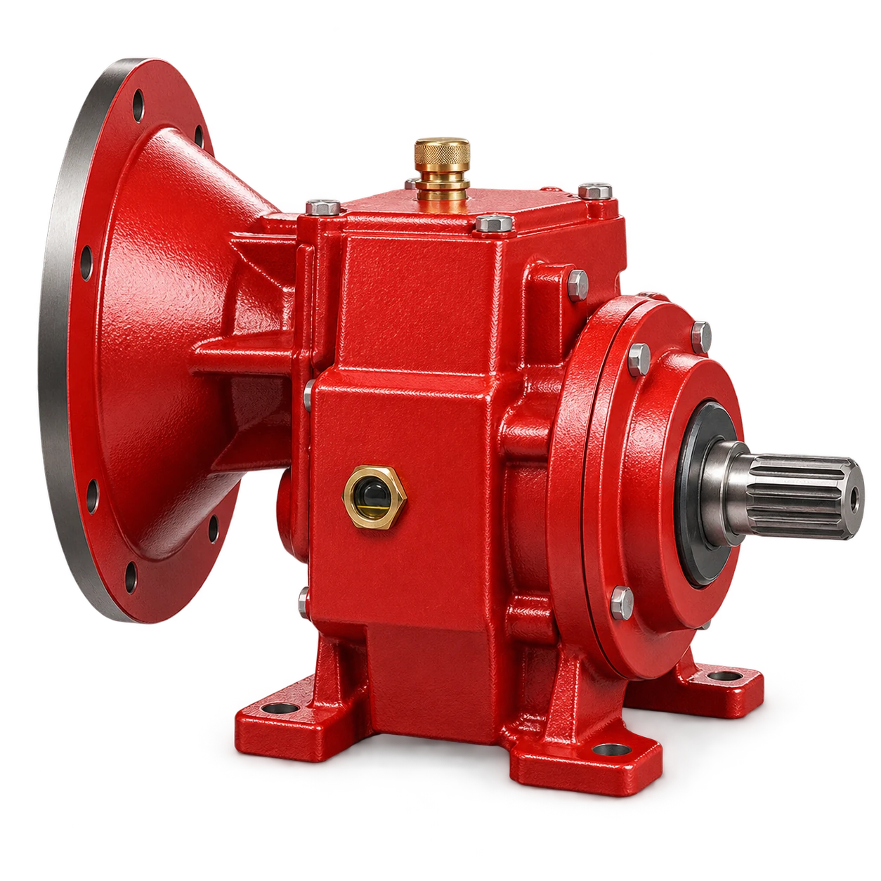
The RM Gear Reducer is an industrial reducer family for conveying and process equipment. Its catalog selection basis is motor power, reduction ratio, output torque and mounting dimensions. The catalog does not publish one ratio or torque rating that suits every application, so the selected unit requires a supplier-confirmed data sheet for the operating point.
Freeze the driven-machine requirements
Do not start with a gearbox table until the load is defined. Record:
| Input | What the value must represent |
|---|---|
| Required output speed | Normal speed plus minimum, maximum and tolerance |
| Motor speed | Actual rated speed at supply frequency, not synchronous speed alone |
| Operating torque | Verified steady or time-weighted demand at the reducer output |
| Peak torque | Startup, acceleration, reversal, braking, jam or process upset |
| Duty | Starts per hour, running hours, cycle profile and direction changes |
| External loads | Radial and axial forces from sprockets, pulleys, couplings or screws |
| Environment | Ambient temperature, dust, washdown, altitude and hazardous area |
| Installation | Shaft arrangement, mounting position, space and maintenance access |
Identify whether every power and torque value is stated at the motor input or reducer output. NORD’s drive selection and configuration page identifies ambient conditions, motor power, output speed and output torque as selection inputs and provides unit-specific documentation. Mixing input and output values is a common source of a plausible-looking but invalid selection.
Calculate the initial ratio and output speed
For a simple reducer:
i = n₁ / n₂
where i is reduction ratio, n₁ is input speed and n₂ is output speed. Rearranged:
n₂ = n₁ / i
Assume an actual motor speed of 1,470 rpm and a required driven speed of 58 rpm:
i = 1,470 / 58 = 25.34
If the nearest available exact catalog ratio is 25.0, the expected output speed is:
n₂ = 1,470 / 25.0 = 58.8 rpm
These are hypothetical values, not RM product data. The driven equipment owner must decide whether 58.8 rpm is acceptable. A conveyor may change capacity; a dosing device may change feed rate; a mixer may change tool speed and process energy. Do not force a nearby ratio into service without checking the process consequence.
Use actual motor speed for final calculations. An induction motor nameplate speed varies with pole count, frequency and load. A VFD expands the speed range but introduces minimum-speed cooling, maximum motor speed, field-weakening and resonance checks. Ratio selection cannot delegate those limits to the control system.
Check torque at the selected ratio
Power and speed can be converted to ideal shaft torque using:
T = 9,550 × P / n
where T is torque in N·m, P is power in kW and n is speed in rpm. For a hypothetical 11 kW motor at 1,470 rpm:
T₁ = 9,550 × 11 / 1,470 = 71.5 N·m
With ratio 25.0 and an assumed 94% efficiency used only for this example:
T₂ = 71.5 × 25.0 × 0.94 = 1,680 N·m
This result is an estimated available running torque, not an allowable gearbox rating and not a guaranteed motor starting torque. Confirm the efficiency at the operating point, motor torque curve, drive limits and the reducer’s permitted output torque. The selected motor must not drive more torque through the reducer than the reducer, shafts and driven machine can accept.
SEW-EURODRIVE’s drive project-planning manual treats maximum output torque as a primary gear-unit selection criterion and then chooses a ratio near the calculated ideal value. It also warns that permitted torque can vary with ratio. A housing size that works at one ratio is not automatically valid at another.
Apply duty and peak loads without double counting
Separate three quantities:
- process operating torque: what the driven machine needs in established operation;
- maximum application torque: the highest credible startup, acceleration or upset demand;
- gear-unit rating: the supplier’s permitted continuous and short-duration torque at the exact ratio.
Use the reducer manufacturer’s service-factor method. Do not multiply several undocumented margins simply because each sounds conservative, and do not omit peak events because a service factor was applied. Ask whether the catalog factor already covers hours per day, starts, load class and prime mover, then check special loads outside that method.
The related gearbox service-factor guide explains this distinction in more detail. It is especially important for conveyors, mixers and feeders that may start loaded. A continuously flood-loaded screw beneath a hopper or silo is a screw feeder, not merely a control-fed conveyor; head pressure, material flowability and the worst credible restart belong in the system load case.
Complete the checks that ratio does not answer
Ratio and torque are necessary but incomplete. Review each of these against the exact supplier data:
- Thermal capacity. Continuous power loss must be rejected at the actual ambient temperature, airflow, mounting and duty. Mechanical torque capacity can exceed thermal capacity.
- Radial and axial load. A pulley or sprocket creates force and bending moment at the output shaft. Position, diameter and direction matter.
- Mounting position. Orientation can change oil quantity, level port, breather and lubrication provisions.
- Input limits. Check maximum input power, speed and motor mass or adapter limits.
- Output interface. Confirm shaft diameter, key or shrink connection, coupling and allowable backlash where relevant.
- Starts and reversals. Verify short-duration torque, brake or backstop action and the complete control sequence.
The NORD G1000 constant-speed gear-unit catalogue portal provides the current regional catalog downloads. Its rating-table structure illustrates why a requested ratio must be checked against the applicable output torque, motor power, efficiency and permitted shaft loads instead of inferred from nominal motor power.
For shaft-mounted arrangements, the installation guide for belt-conveyor gearboxes covers shaft fit, torque-arm reaction, lubrication orientation and guarding. Selection and installation are separate gates: a correctly sized reducer can still fail if its torque arm binds or its lubricant configuration belongs to another mounting position.
Use a procurement and acceptance checklist
Issue the supplier a duty sheet rather than a ratio alone. Require the returned proposal to identify:
- exact reducer model and exact ratio;
- output speed at the stated motor operating point;
- continuous and peak output-torque ratings;
- applied service factor and its stated basis;
- thermal rating and any assumed ambient or cooling;
- permitted radial and axial loads at the actual load position;
- mounting position, lubricant and breather arrangement;
- shaft, flange, key, coupling and motor-adapter interfaces;
- direction of rotation and backstop or brake requirements;
- applicable drawings, manuals and nameplate data.
At commissioning, verify identity, ratio and rotation before coupling to a hazardous load where practical. Check guards, oil configuration and fasteners, then progress through no-load and controlled-load stages while recording input current, output speed, temperature, noise and leakage. Use project-specific limits and a stable operating condition.
Servicing or uncoupling a drive exposes electrical and mechanical energy. OSHA’s hazardous-energy guidance requires control of unexpected startup and stored energy; the site’s procedure must cover the driven load, gravity, pressure, tension and back-driving as applicable.
Conclusion
Reliable gear reducer ratio selection links required output speed to the exact catalog ratio, then proves continuous and peak torque, service duty, thermal capacity, shaft loads and mounting constraints. Power or ratio alone cannot approve the drive. Send the supplier a complete duty sheet and retain the returned operating-point data for commissioning. To compare the catalog family with your inputs, view the RM gear reducer details.