
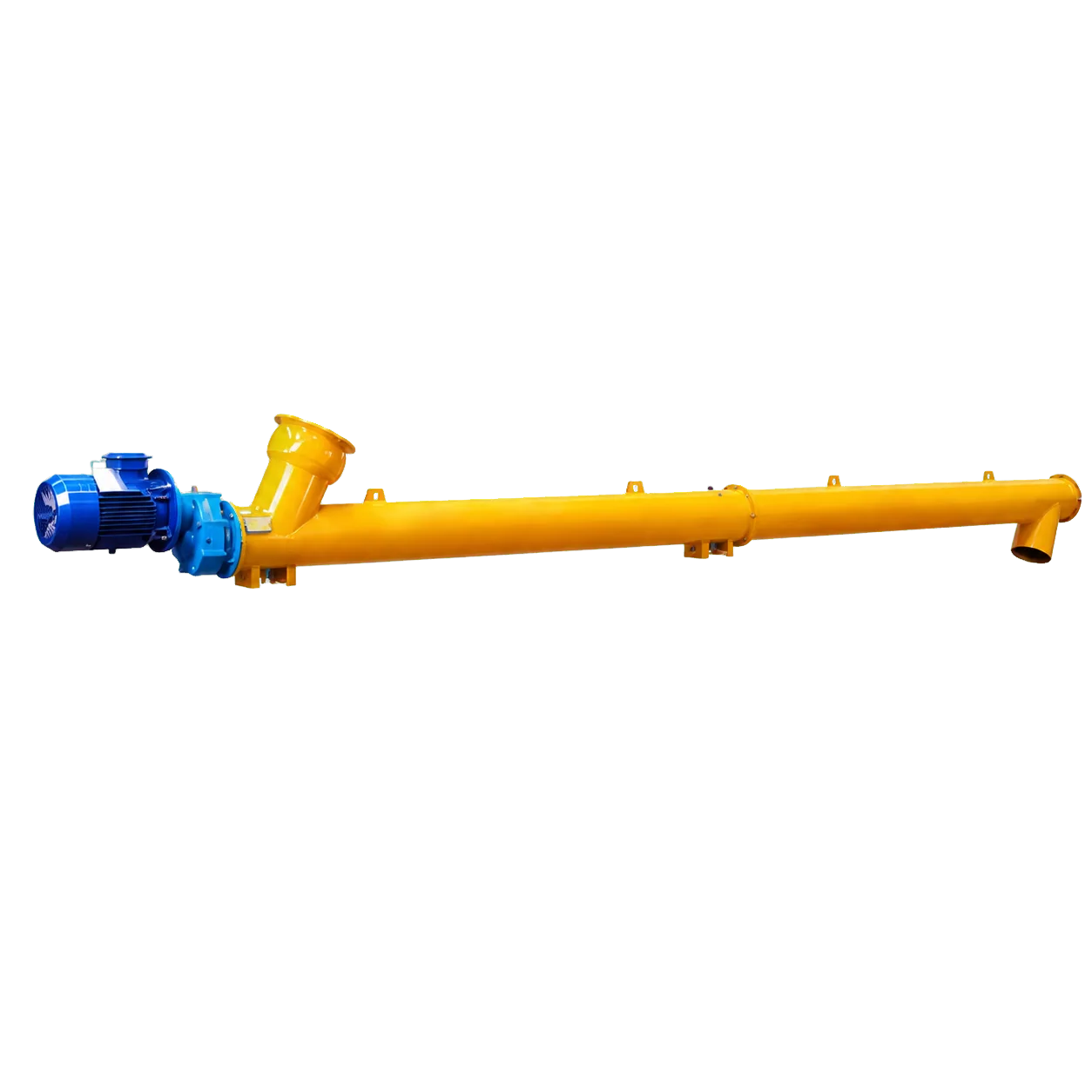
A cement screw conveyor gearbox service factor is not a reserve-torque percentage that can be chosen in isolation. Select the reducer from calculated running and restart torque, load pattern, starts per hour, operating hours, mounting position, temperature, peak-load limit and thermal capacity.
VOGO’s project-specific cement screw conveyor drives are configured with the complete duty. The product page does not assign one reducer or service factor to every application.
Cement Screw Conveyor Gearbox Service Factor Checks
| Check | Question |
|---|---|
| Motor power | Can the motor supply continuous power after derating? |
| Output torque | Can the reducer carry normal shaft torque? |
| Peak torque | Can it withstand the defined start or upset for the allowed duration? |
| Service factor | Does the selection method cover load class, hours and starts? |
| Thermal rating | Can heat be rejected at the actual speed, load and ambient? |
| Connected parts | Can coupling, key, shaft and screw carry the same torque? |
The KWS horsepower guide calculates empty and material power for conveyor duty. Convert final shaft power to torque, then add explicit restart cases. A factor cannot convert a running calculation into a verified flood-loaded feeder restart.
Build the Application Classification
Give the reducer supplier normal torque, maximum operating torque, loaded-start torque, start frequency, daily hours, shock character, screw speed, motor power, VFD ramps, mounting position, ambient temperature and any reverse/jog duty.
If the screw sits under a silo with a continuously covered inlet, identify screw feeder duty. Head load and inlet shear must be calculated through the silo discharge design process. Do not simply increase a conveyor service factor.
SEW-EURODRIVE project-planning guidance uses application-specific load and motor data. Follow the method for the actual reducer family; factors differ between catalogs.
Worked Torque Comparison
Assume a screw requires 1,100 N·m continuously and 1,750 N·m for a defined six-second loaded start. The reducer must satisfy:
- continuous output torque at least 1,100 N·m;
- permitted peak torque at least 1,750 N·m for that duration and frequency;
- the manufacturer’s required service factor;
- thermal capacity at operating speed and ambient;
- connected-component capacity at 1,750 N·m or the defined protective limit.
These are example loads, not VOGO ratings. Selecting a reducer with 1,750 N·m nominal torque may be conservative, but selecting one from service factor alone is not traceable.
Mounting, Lubrication and Commissioning
Mounting orientation affects oil level, breather position and bearing lubrication. The SEW P.MC instructions require checking nameplate data, oil level, mounting position, noise, vibration and leakage; its intervals apply to that product family only.
Commissioning should verify direction, guards, oil, breather, alignment, unloaded current, loaded current, temperatures, leakage and trip response. A VFD ramp should reduce shock without extending acceleration into a motor thermal problem.
The startup torque guide defines the load cases that belong on the reducer sheet.
Understand What Service Factor Can and Cannot Do
A reducer service factor usually compares a rated mechanical capacity with an application demand under defined assumptions. It can account for load character and operating regime within the manufacturer’s method. It cannot validate an unknown load, compensate for an uncalculated feeder head, or authorize operation above peak torque.
Do not compare service-factor numbers from different manufacturers without their definitions. One catalog may embed motor type, operating hours or start frequency differently from another. Ask each supplier for the selected rating method and the resulting available margin at the stated output speed.
Check Thermal Capacity at Low Output Speed
Mechanical torque capacity and thermal capacity are different. A reducer can be mechanically strong enough but unable to reject heat continuously at low speed, high ambient temperature or restricted ventilation. VFD operation can extend time at these conditions.
Provide ambient minimum and maximum, indoor/outdoor location, solar exposure, dust accumulation, installation altitude, duty cycle and nearby heat sources. The drive supplier may require a fan, oil cooler, different lubricant or a larger casing. Do not assume a larger motor solves reducer heating.
Consider Overhung and External Loads
A shaft-mounted reducer, chain drive or belt drive can impose radial and bending loads on the drive shaft and end bearing. A torque arm must react reducer torque through a stable support while allowing the intended movement. Mispositioned torque arms can load the shaft or casing.
Record sprocket or sheave diameter, center distance, belt/chain tension, reducer mass, mounting geometry and thrust-bearing location. Verify end-bearing radial and thrust capacity. The gearbox service factor does not cover an unverified overhung load.
Gearbox Selection Worksheet
| Item | Normal value | Governing value | Source |
|---|---|---|---|
| Screw speed | Project input | Maximum/minimum | Capacity calculation |
| Continuous torque | Calculated | Highest normal material case | Conveyor calculation |
| Start torque | Calculated | Settled or flood-loaded restart | Load-case register |
| Starts per hour | Operating plan | Maximum credible | Controls narrative |
| Daily hours | Operating plan | Maximum | Production schedule |
| Ambient temperature | Site data | Seasonal maximum | Project specification |
| Mounting position | Drawing | Fixed | General arrangement |
| Protective torque | Controls | Weakest approved part | Component schedule |
Require units and time duration for every peak value. “High torque” and “heavy duty” are not engineering data.
Failure Clues After Commissioning
High oil temperature with acceptable motor current suggests lubrication, thermal capacity, mounting or reducer condition. High current and normal reducer temperature may indicate material or mechanical overload. Oil leakage can follow incorrect breather position, overfill, damaged seals or pressure. Repeated coupling failures may reflect alignment or drive movement rather than reducer size.
Trend temperature, vibration, noise, oil condition and load. Use the delivered manual for alarm limits and maintenance intervals. A generic article cannot set a safe temperature for every oil and gearbox family.
Information Required From the Reducer Supplier
Request the exact reducer model, ratio, mounting position, lubricant, nominal output torque, permitted peak torque with duration, calculated service factor, thermal rating at site ambient, overhung-load capacity, efficiency and maintenance schedule. Record any required cooling or breather arrangement.
The conveyor supplier should then confirm that the drive’s protective torque remains below the screw, shaft, coupling and bolt limits. This closes the interface between catalog reducer selection and mechanical conveyor design before final approval.
Comparison Example for Two Reducer Offers
Offer A may show a higher nominal torque but no thermal confirmation at low speed. Offer B may show lower nominal torque yet document adequate continuous, peak and thermal capacity with a cooling fan. The better selection is the one that passes every stated load case, not the one with the larger headline number.
Normalize both offers to screw-shaft speed, site ambient, duty hours and the same restart torque. Record exclusions such as customer-supplied coupling, oil cooler or torque arm so cost comparisons include the complete drive package.
Conclusion
Select the cement screw conveyor gearbox service factor only after calculating continuous, loaded-start and upset torque. Check nominal, peak and thermal reducer limits, mounting and lubrication, then verify the coupling and shaft at the same protective torque. Ask the drive supplier to record the application classification and governing limit in the proposal.