Silo aeration pad placement should follow the powder’s actual flow problem and the hopper geometry, not a copied spacing diagram. Locate pads in the stagnant hopper region, distribute air through suitable powder without creating a direct path to the outlet, and commission with the lowest effective regulated airflow. At the same time, prove that the silo filter, pressure alarm and relief path can manage the added air.
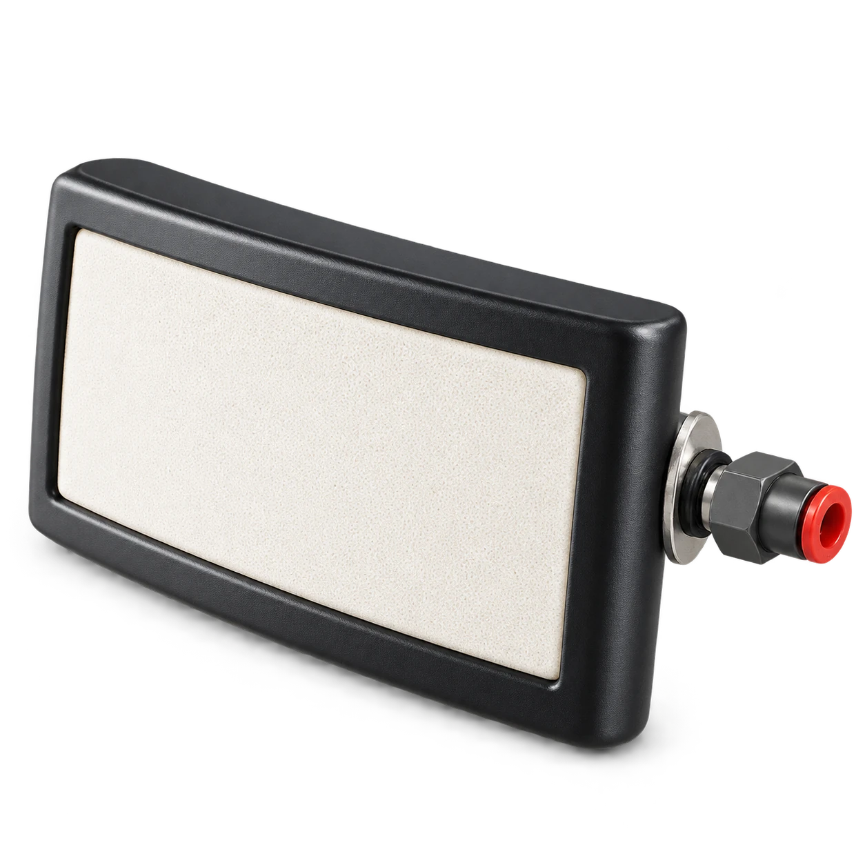
The PL air fluidization pad is a compact flow-assistance product with a catalog working-pressure range of 0.2–0.3 MPa. Selection is based on hopper geometry, powder behavior, air pressure and air quantity. That pressure range is product data, not an instruction to apply the same pressure at every pad; the complete regulator, pipe losses, pad arrangement and silo limits require confirmation.
Confirm that aeration suits the powder
Aeration reduces the effective friction and consolidation of some fine powders by introducing gas between particles. It can help cement, fly ash and similar materials flow from a hopper, but “powder” alone does not prove suitability. Moisture, particle-size distribution, permeability, time at rest and compaction all change the response.
The Wiley chapter Hopper/Bin Design distinguishes flow pattern, arching, ratholing, flow rate and segregation, and treats aerated and non-aerated discharge as different design cases. That distinction matters: a pad may restart local flow while the vessel still has a funnel-flow pattern and stagnant material elsewhere.
Collect evidence before adding hardware:
| Observation | Likely question |
|---|---|
| Stable rathole above the outlet | Is the outlet too small for the material’s cohesive strength? |
| Intermittent arch that collapses after impact | Does the powder compact during storage or vibration? |
| Flow only near one wall | Is the outlet eccentric or is air distribution uneven? |
| Sudden uncontrolled discharge after aeration | Is the material over-aerated or is the downstream feeder undersized? |
| Problem appears after humid weather | Has permeability or wall friction changed with moisture? |
If the material is highly cohesive, wet, fibrous, coarse or prone to segregation, obtain representative flow-property testing. Aeration does not enlarge an undersized outlet, change the hopper angle or turn funnel flow into mass flow by declaration.
Silo aeration pad placement by hopper geometry
Use operating records, safe internal inspection when the vessel is empty, wall-temperature or pressure observations where appropriate, and discharge behavior to locate the failure. Do not assume every hopper needs a uniform carpet of pads.
For a conical hopper, pads are commonly arranged in circumferential rows so their effective zones overlap in the problem region. For pyramidal or rectangular hoppers, wall panels and corners may need different coverage. Keep each pad accessible from outside where possible and avoid weld seams, stiffeners, level devices and outlet hardware.
Placement objectives are:
- introduce air below or within the stagnant region;
- cover the active hopper walls without large untreated gaps;
- avoid directing air straight into the outlet or feeder;
- divide the arrangement into controllable zones;
- permit isolation, cleaning and replacement.
Monitor Technologies’ rectangular air pad data gives manufacturer-specific examples for rows, spacing and air consumption. Those figures describe Monitor products. They are useful evidence that coverage and air demand are device-dependent, but they must not be copied as PL spacing or pressure limits.
Size the air system as a complete circuit
The air supply must deliver the required flow at the pads after losses through the regulator, valves, manifolds and tubing. A pressure gauge at the supply header alone cannot prove the pressure at the most remote pad.
Prepare a schedule for each zone:
- number and model of pads;
- required pressure and air quantity from the selected supplier;
- line size, length and fittings;
- regulator and relief arrangement;
- solenoid or manual valve state on power loss;
- filter, water separator and drain;
- pressure indication at a representative downstream point;
- expected operating sequence and duty cycle.
Clean, dry air matters because water or oil can blind a porous element and change the powder. The Mineral Products Association’s silo safety guide includes dry compressed air and removal of oil or water contamination among maintenance checks for silo systems.
Do not compare a compressor’s free-air delivery directly with a pad’s consumption at pressure without putting both values on the same reference basis. Include simultaneous zones, leakage and minimum supply pressure, then verify regulator capacity at the calculated flow.
Protect the silo from added air
Every unit of aeration air entering the hopper must leave the vessel. Check the vent filter, pressure indication, alarms and pressure relief device against all air sources that can operate together. A pad does not make a silo airtight or pressure rated.
The MPA guide explains that inadequate venting can over-pressurize powder silos and identifies filters, alarms, automatic shutoff and relief valves as parts of the protection system. Although its main case is pneumatic tanker filling, the system principle also applies to auxiliary aeration: identify the maximum credible incoming airflow and verify a safe outlet path.
Before commissioning, establish interlocks or operating rules for:
- aeration during pneumatic filling;
- multiple aeration zones energized together;
- blinded or offline vent filters;
- high silo pressure or filter differential pressure;
- high material level;
- loss of downstream receiving capacity.
The silo pressure relief valve inspection guide explains why a relief valve is the last protective layer, not a normal airflow-control device. The silo dust collector sizing guide covers filter duty and fill-air surges.
Commission one zone at a time
Use a controlled trial with a known material condition and a receiving system able to handle the discharge. Record silo level, time at rest, downstream feeder state and ambient conditions so a later trial can be compared.
- Inspect pad orientation, fasteners, external hoses and isolation valves.
- Confirm the filter and pressure-protection system is available.
- Start the downstream conveyor, feeder or valve in its approved sequence.
- Apply the lowest supplier-approved pressure to the lowest required zone.
- Observe discharge onset, stability, dust-filter response and silo pressure.
- Add zones or increase the setting only when evidence shows insufficient coverage.
- Stop air and record whether flow stops, remains stable or surges.
Do not commission by opening every valve fully. Excess air can fluidize material above the intended zone, increase filter loading, create a sudden flood into the outlet or make downstream dosing unstable.
Trial example: a hopper has two lower and two upper zones. With all values within the selected pad documentation, start one lower zone for 10 seconds and measure discharge rate over a fixed interval. Repeat with both lower zones, then add the upper zone only if the stagnant region remains. The times and sequence are hypothetical test inputs—not PL settings. Retain the combination that gives stable discharge at the lowest air demand while pressure protection remains normal.
Diagnose poor response from measured symptoms
| Symptom | Check before increasing pressure |
|---|---|
| No improvement | Closed valve, blocked line, wet pad, wrong zone or non-aeratable material |
| Flow improves only near one wall | Uneven manifold loss, missing coverage or asymmetric hopper geometry |
| Discharge pulses | On/off timing, outlet restriction, feeder capacity or excessive air |
| Filter differential pressure rises | Simultaneous airflow, blinded media or insufficient filter capacity |
| Material floods after delay | Stored aeration, collapsing rathole or downstream control mismatch |
| Air use is higher than expected | Leaks, failed regulator, broken tubing or porous element damage |
Pressure alone is a weak diagnostic. Measure flow where practical, compare zones, and inspect the air-quality train. If added air produces little response, revisit the flow-property and hopper-design assumptions rather than continuing to raise pressure.
Maintain pads without releasing stored material
Pad service can expose compressed air, electrical valve energy and a column of bulk material. Isolate and depressurize the air header, lock out automatic valves, and secure the vessel against material movement before loosening any fitting. OSHA’s hazardous-energy guidance covers pneumatic, mechanical and other stored energy during service.
Track air consumption, pressure, response time and discharge behavior. A gradual rise in pressure at the same result can indicate pad blinding or line restriction. Inspect drains, filter elements, hoses, check valves and manifolds. Replace parts by the selected manufacturer’s method; drilling or scraping a porous face can alter distribution and create a jet.
Acceptance checklist
The handover package should contain:
- powder identification and relevant flow-test data;
- hopper drawing with pad locations and numbered zones;
- pad model, quantity and supplier-approved operating range;
- air-balance calculation and regulator settings;
- clean-air equipment and drain schedule;
- vent-filter, pressure-alarm and relief-system checks;
- valve fail states and operating sequence;
- commissioning records for flow, pressure and material response;
- safe isolation and inspection procedure.
Acceptance should state the tested material, level and storage time. A successful trial with fresh, dry powder does not automatically validate a long-storage or high-moisture case.
Conclusion
Effective silo aeration pad placement targets a verified stagnant region in a material that responds to aeration. Arrange controllable zones from the hopper geometry, size the clean-air circuit using the selected pad data, and commission at the lowest effective airflow while monitoring discharge, filters and silo pressure. The PL pad can assist flow, but it cannot replace sound hopper geometry, a capable outlet or the silo’s venting and pressure-protection system.