Vibrator motor frequency selection should begin with the motion required by the machine, not the motor’s kW or a convenient mounting footprint. Match mechanical speed, excitation force, load and supporting structure, then check the electrical supply and permitted operating range. Two motors with similar power can produce different process motion.
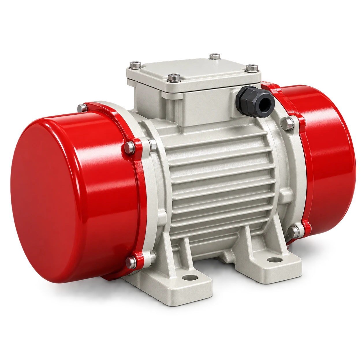
The MVE industrial vibrator motor table currently lists five models with 1–8 kN excitation force and 2800 rpm shaft speed. These are catalog facts, not evidence that every hopper, screen or feeder should run at that speed. Confirm the selected motor and driven equipment as a system. Do not assume that another manufacturer’s MVE designation identifies the same product.
Distinguish mechanical and electrical frequency
For a rotating-unbalance vibrator producing one excitation cycle per shaft revolution:
Mechanical frequency, f = n / 60
Here n is actual shaft speed in rpm and f is cycles per second, or Hz. A hypothetical 1800 rpm shaft produces 30 Hz mechanical excitation; 900 rpm produces 15 Hz. The catalog’s 2800 rpm corresponds to about 46.7 Hz. This conversion does not predict stroke, material flow or a safe structural response.
Electrical supply Hz belongs to the motor’s electrical operating conditions. Do not enter a 50 Hz supply value into a mechanical motion calculation without checking the shaft speed. Use the nameplate, approved motor data and measured speed where required.
The Martin MM technical table separates speed, centrifugal force, supply frequency and voltage. It illustrates why these fields belong on a selection sheet. Its speed classes and force values apply to Martin products, not the VOGO MVE range.
Define the driven equipment before choosing a motor
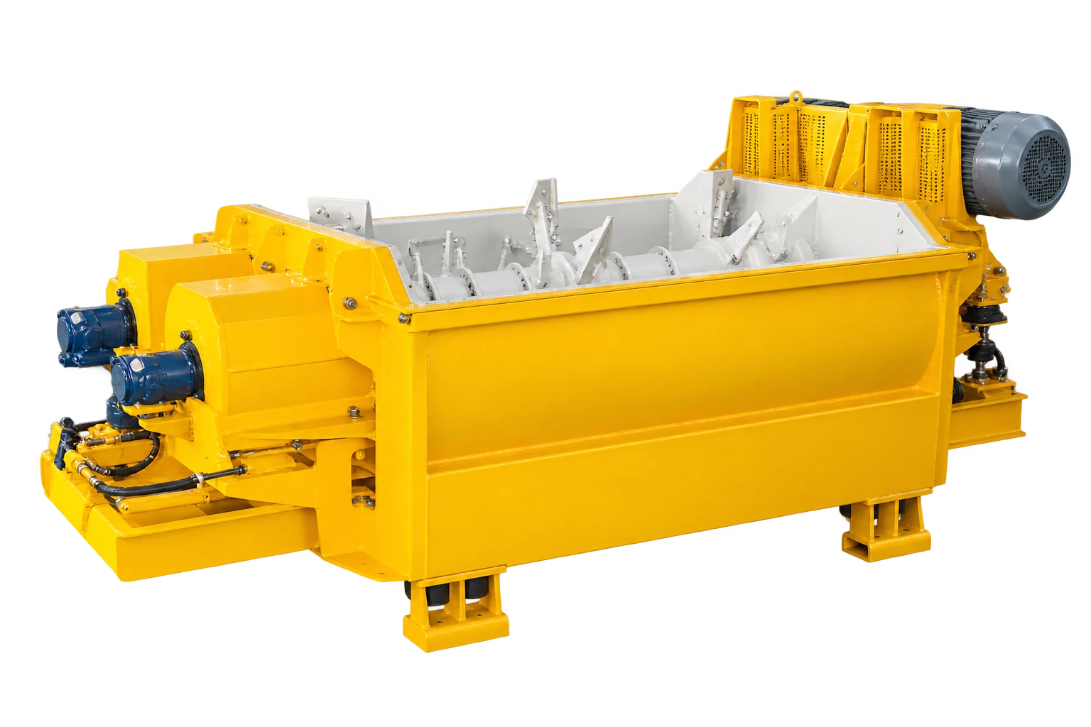
A hopper flow aid, a spring-supported feeder and a screen have different objectives and structural arrangements. Specify whether the motor excites a local wall or a deliberately vibrating assembly. Obtain the equipment designer’s required direction of motion, operating speed range and force basis.
For a replacement, record the original motor’s complete nameplate and arrangement, not just the power. Changes in mass, mounting stiffness, material load or motor quantity can invalidate a replacement selected from dimensions alone. If the original selection is unknown, have the system reviewed rather than guessing from the largest available motor.
Use this engineering selection checklist:
| Input | Why the selection needs it |
|---|---|
| Process objective | Flow assistance, transport, screening or another defined result |
| Motion | Required direction, stroke basis and operating-speed envelope |
| Structure and load | Equipment mass, material inventory, springs, supports and stiffness |
| Excitation | Force per motor, quantity, mounting orientation and approved pairing |
| Electrical duty | Voltage, supply frequency, starting method, current and duty cycle |
| Environment | Ambient conditions, ingress exposure and assessed hazardous-area requirements |
| Interfaces | Mounting, access, cable movement and protective arrangements |
A force value expressed as kgf is not a supported material mass in kg. Resolve ambiguous units before comparison; request a force in N or kN and identify whether it refers to one motor or a system resultant.
Compare candidates at the required operating point
Do not rank candidates by maximum force alone. Ask whether each motor can deliver the required motion at an approved speed without exceeding its current, mounting or equipment limits. A high-force option that only works outside its permitted range is not a suitable shortlist entry.
For illustration, suppose an equipment designer requires 30 Hz mechanical excitation. A fixed-speed 2800 rpm motor gives approximately 46.7 Hz, so matching its force or bolt pattern does not establish equivalence. This is a hypothetical selection rejection, not permission to slow an MVE motor with an unapproved inverter.
Treat a VFD proposal as a separate verification
The Mooser operating manual calls for type-specific approval of maximum frequency and warns of excessive centrifugal forces when frequency is increased. The Martin electric-vibrator manual prohibits exceeding its motor’s nameplate frequency and requires current checks through the operating range. These instructions differ in detail and must not be merged into a universal VOGO setting.
Obtain written limits for the actual motor, including allowed speed range, eccentric setting, thermal duty, starting and stopping, and protection. The equipment designer must also assess structural response through startup, operation and rundown. Reducing electrical frequency does not automatically establish safe process motion.
For a two-motor arrangement, require the designer’s specified rotation, synchronization behavior and fault-stop logic. Do not assume two independent speed commands guarantee the intended motion.
Make the acceptance test observable
Agree a witnessed trial with the representative load and approved guards fitted. Record speed, each motor’s line current, intended process result and observations at the mounting and surrounding structure. Define who may authorize changes and the stop conditions before testing.
Stop for abnormal structural motion, loosened fasteners, damaged connections, overcurrent or an unexpected process response. Use the manufacturer’s limits; this article supplies no generic acceleration, temperature or vibration threshold.
OSHA 1910.147 addresses unexpected startup and stored energy during servicing. Isolate before touching weights, mounts or wiring. A drive stop command is not an isolation point. After selection, use the separate vibrator force-adjustment guide for the commissioning workflow, not as a substitute for design approval.
Conclusion
Vibrator motor frequency selection is a motion-and-load decision followed by electrical and mechanical checks. Keep supply Hz, shaft rpm and excitation force separate. Reject an apparent replacement that cannot meet the required operating point within approved limits, even when its power and mounting dimensions match.