
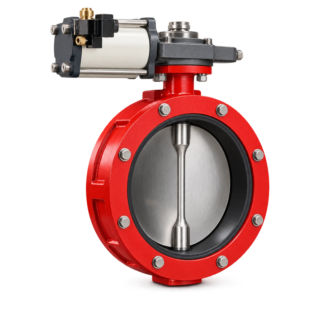
Pneumatic vs electric butterfly valve actuator selection should begin with the plant utilities, required operating pattern and defined behavior after a failure. Choose a complete assembly that can perform that duty, rather than assuming pneumatic means fast and safe or electric means precise. For powder service, the valve’s load and process role remain part of the decision.
The VOGO cement butterfly valve catalog lists manual, pneumatic and electric actuation choices. It does not identify a universal actuator model, operating time, duty cycle or supplied fail-safe package. This comparison helps define the technology choice for on/off powder isolation; it does not approve a metering application or replace assembly-specific sizing.
Compare available utilities at the valve, not in the plant brochure
For a pneumatic proposal, record the air supply at the actuator during simultaneous plant demand, the required air quality, line route and the proposed control accessories. Compressor nameplate pressure is not proof of the pressure available during a stroke. Include the utility owner in the review so that an actuator quotation does not conceal an unfunded air-system extension.
For an electric proposal, record voltage, frequency or DC supply, control architecture, cable route, environmental exposure and any required backup supply. State whether the mechanism only opens and closes occasionally or follows frequent commands. Ask for the offered unit’s documented operating-time and duty limits, not a general comparison-table value.
The Bray Series 92/93 pneumatic IOM distinguishes double-acting and spring-return mechanisms and specifies its operating air requirements. The Bray Series 70 electric IOM documents an electric drive and its protective/control features. These manuals illustrate configuration-dependent engineering; their ratings and features are not VOGO specifications or evidence of an approved VOGO/Bray combination.
Pneumatic vs electric butterfly valve actuator decision matrix
This recommended matrix compares project evidence, not universal winners. Give each requirement an owner and ask both bidders to answer against the same duty. A rejected utility or failure requirement should not be averaged away by a favorable purchase price.
| Project question | Pneumatic proposal | Electric proposal |
|---|---|---|
| Utility at point of use | Demonstrate available air during demand and air-treatment scope | Confirm supply and electrical installation scope |
| Operating pattern | Confirm stroke demand, air consumption basis and accessory suitability | Confirm operating time, command frequency and duty limits |
| Loss of utility | Identify double-acting or stored-energy arrangement and resulting movement | Identify behavior without power and any specified backup mechanism |
| Control interface | Define solenoid, position indication and any other accessories | Define control inputs, position indication and local controls |
| Site environment | Confirm the complete assembly’s suitability | Confirm the complete assembly’s suitability |
| Installed cost boundary | Include air lines, treatment, wiring and commissioning | Include cabling, controls, backup if required and commissioning |
| Approval basis | Documented assembly and site acceptance requirements | Documented assembly and site acceptance requirements |
Actuator technology alone does not establish the valve’s safe failure position. A spring-return option needs a specified action and sufficient capability under the defined valve load. A double-acting unit is not automatically a stored-energy return system. Likewise, an electric actuator does not acquire a guaranteed emergency movement simply because its normal operation is motorized.
A commanded valve position and a confirmed valve position are different control signals. Define how the control system distinguishes a request to close from evidence of actual travel. Decide which feedback is needed for the process sequence and how loss of signal is handled. This is a control-system requirement, not a feature that can be inferred from an actuator’s power source.
Two plant scenarios lead to different shortlists
Illustrative scenario A: an existing batch plant with instrument air. The plant has a documented air supply at the proposed valve location and an approved requirement for movement to a defined position after loss of air. A suitable pneumatic stored-energy arrangement is a candidate. The shortlist still depends on the valve load, the specified failure action, control accessories and installation evidence. Existing air infrastructure alone does not approve the assembly.
Illustrative scenario B: a remote powder transfer point without an air network. Electrical supply is available and the process calls for occasional on/off operation. An electric proposal may avoid building an air utility solely for that valve. If an assessed failure case requires movement without normal power, the proposal must include an explicitly verified way to achieve it; otherwise it fails that requirement. These scenarios are decision examples, not VOGO installations or cost-saving claims.
Do not label “fail closed” as universally safest. Closing may interrupt upstream delivery, trap material or conflict with another protective function. The responsible process and safety assessment must define the required state and sequence. This comparison does not assign a safety integrity level, explosion classification or certification to either technology.
Separate technology selection from torque approval
A drive type can pass the utility review and still fail the loaded-valve duty. Declare powder properties, material head, differential pressure where relevant, deposits, idle periods and the required movement. Do not transfer a clean-water torque value to a disc operating under powder without the valve supplier’s approval.
The butterfly valve actuator torque guide addresses breakaway, running and seating requirements and the supplied actuator’s output basis. Use that separate check after defining the technology shortlist. Matching the mounting interface alone does not approve the load, shaft connection or assembly.
Neither actuation method makes a catalog valve pressure-rated, airtight, suitable for combustible dust or capable of accurate powder metering by default. Obtain the relevant assembly documentation for the actual environment. A normal dust enclosure is not proof of explosion protection, and a valve position signal is not proof of zero material leakage.
Define handover and isolation responsibilities
A useful procurement handover names the utility owner, controls integrator, assembly supplier and party responsible for site testing. Include drawings, wiring or pneumatic diagrams, operating limits, declared failure behavior and unresolved deviations. Compare installed scope only after mandatory requirements have been answered.
Maintenance requires its own energy-control procedure. The US OSHA hazardous-energy overview identifies electrical, pneumatic and other stored-energy hazards. An actuator may retain spring energy or move when a utility is restored. A selected failure position or local stop does not replace isolation, verification and the site’s authorized safe-work procedure.
Is a pneumatic actuator automatically safer than an electric actuator?
No. Safety depends on the assessed process state, the complete actuator and control arrangement, and evidence for the specified loss-of-utility cases.
Conclusion
Pneumatic vs electric butterfly valve actuator comparison is most useful when it removes unsuitable options using real utility, operating-pattern and failure-state requirements. Follow that shortlist with loaded-valve sizing and complete-assembly approval. The defensible choice is the documented fit to the installation, not a technology label or an assumed universal advantage.