
Diagnose pulse-jet cleaning in signal order: controller demand, electrical output, solenoid pilot, pilot exhaust, diaphragm valve and compressed-air delivery. First decide whether every valve, one zone or one valve is affected. That split prevents replacing a diaphragm when the real fault is a shared power, interlock or air-supply problem.
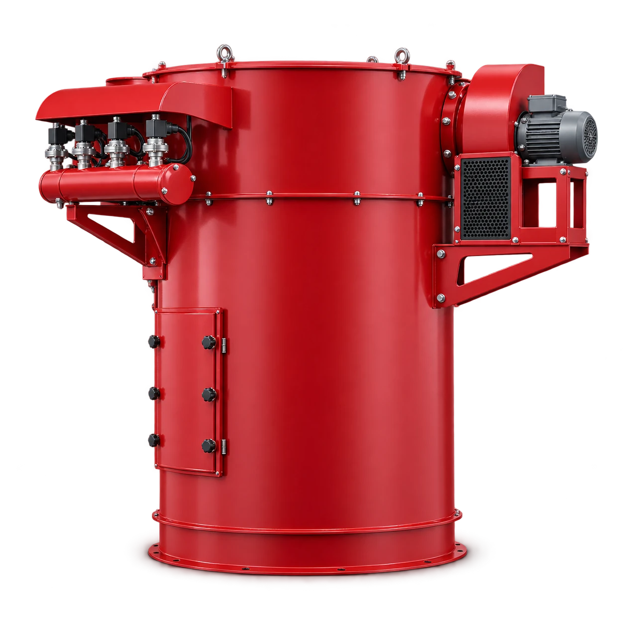
The DSC pulse-cleaned dust collector is cataloged by airflow, filtration area and silo capacity. The public catalog does not identify every controller or valve variant. Use the wiring diagram, valve model and installation manual supplied with the actual collector before measuring or replacing parts.
Make the symptom repeatable
Record whether the symptom is no pulse, weak pulse, continuous air leakage, irregular sequence, high differential pressure, or emission during cleaning. Note whether it affects all rows, one output or one valve and whether the fault follows an output when leads are exchanged by an authorized technician.
Do not diagnose only by sound. A click can occur without a full diaphragm opening, and a pressure gauge can look normal between pulses while the manifold fails to recover during the sequence.
| Observed scope | First shared point to test | Likely next branch |
|---|---|---|
| All valves silent | Supply, interlock, controller power | Input/fuse, inhibit, common air isolation |
| One zone silent | Zone output and common pilot line | Wiring, connector, tubing or local supply |
| One valve silent | Its output, coil and pilot exhaust | Solenoid, pilot path, diaphragm |
| One valve leaks continuously | Pilot sealing and main diaphragm | Debris, wear, damaged diaphragm or tubing |
| Pulses occur but cleaning is weak | Dynamic manifold recovery | Supply restriction, moisture, timing, valve opening |
Follow the command from controller to valve
Donaldson’s Dalamatic troubleshooting sequence distinguishes controller power and output from an isolated solenoid or diaphragm-valve fault. Use an approved meter and the correct wiring diagram to verify supply and output voltage. An indicator lamp is evidence of logic state, not proof that the coil receives the correct voltage under load.
Next verify the solenoid pilot. The Donaldson STi manual describes the pilot valve, actuated by a solenoid, as the control for the main pulse diaphragm valve. Check connector condition, coil identification, pilot exhaust and small pneumatic lines for kinks, blockage or leakage. Confirm voltage, frequency and hazardous-area requirements against the installed nameplate.
Separate pilot action from diaphragm action
A working pilot must change pressure across the main diaphragm quickly enough for the valve to open and close. If the controller output and pilot exhaust are present but the pulse is missing or weak, isolate the system and inspect the model-specific diaphragm, bleed passage, spring and seat.
Donaldson’s Downflo Oval manual lists debris, valve wear, pneumatic tubing faults, diaphragm failure and solenoid leakage or damage as causes of pulse-valve leakage. Emerson describes its ASCO 353 as a pilot-operated diaphragm valve designed for reverse-jet dust-collector pulsing. Those descriptions explain the functional chain; they do not make parts interchangeable across models.
Check air delivery under the sequence
Use the collector manual’s required pressure and air-quality limits. Record manifold pressure before a pulse, its minimum during the pulse and recovery before the next valve. If every pulse weakens progressively, investigate supply capacity, regulator, isolation valve, pipe restriction, moisture and pulse interval before condemning every diaphragm.
The related dust-collector compressed-air requirements guide explains why header volume, peak demand and air quality matter. Static pressure with the system idle does not demonstrate that the valve receives adequate pulse energy.
Moisture or oil can obstruct pilots and shorten diaphragm or filter life. Drain and maintain the air system as specified. Do not simply lengthen pulse duration: it may waste air, prevent recovery or mask a restriction, and the correct setting belongs to the supplied controller and valve.
Use a controlled fault-isolation record
| Test point | Command present? | Physical response? | Recorded evidence |
|---|---|---|---|
| Cleaning demand | Yes / No | Sequence requested | Differential-pressure or timer state |
| Controller output | Yes / No | Output switches | Voltage under load and channel |
| Solenoid pilot | Yes / No | Exhaust changes | Coil/nameplate and tubing condition |
| Main diaphragm | Pilot proven | Valve opens/closes | Pulse sound plus dynamic pressure |
| Manifold | Supply open | Pressure recovers | Before/minimum/recovery trend |
Change one item at a time. Tag removed parts and record the output, valve position and symptom before and after the change. If a fault moves with a tested component, verify compatibility before replacement; if it remains at the position, return to wiring, tubing and manifold branches.
Isolate energy before opening the system
Lock out electrical power, close the compressed-air source and bleed stored pressure before removing a solenoid, cover or diaphragm. Verify zero energy by the site’s procedure. Dust hazards may also require respiratory, ignition-control and housekeeping measures based on the collected material and facility assessment.
After reassembly, restore energy in a controlled manner, leak-test, confirm the sequence and trend differential pressure under representative process load. One successful manual pulse does not prove automatic demand logic or sustained manifold recovery.
Conclusion
Troubleshoot pulse valves as a chain of evidence. Classify the scope, prove controller output, prove pilot action, inspect the diaphragm only after isolation, and measure air recovery during the real sequence. This method narrows the failed stage without inventing a universal pressure or timer setting.
References
Donaldson — Pulse-Jet Filters FS and FT Installation, Operation and Maintenance Manual ↗Donaldson — STi Plus Pulse Timer Range Installation, Operation and Maintenance Manual ↗Donaldson — Downflo Oval DFO 2-4 and 3-6 Installation, Operation and Maintenance Manual ↗Emerson — ASCO Series 353 pulse solenoid valves ↗