Dust collector compressed air requirements must specify air quality, pressure at the cleaning manifold during a pulse, air per pulse and the maximum cleaning sequence. Compressor power or a steady header-gauge reading cannot establish suitability. Treat pulse cleaning as an intermittent demand and include other plant users before purchasing the air supply.
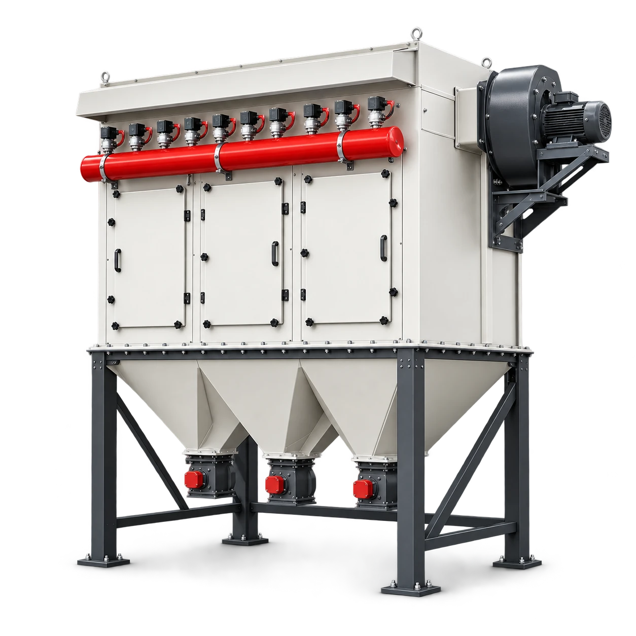
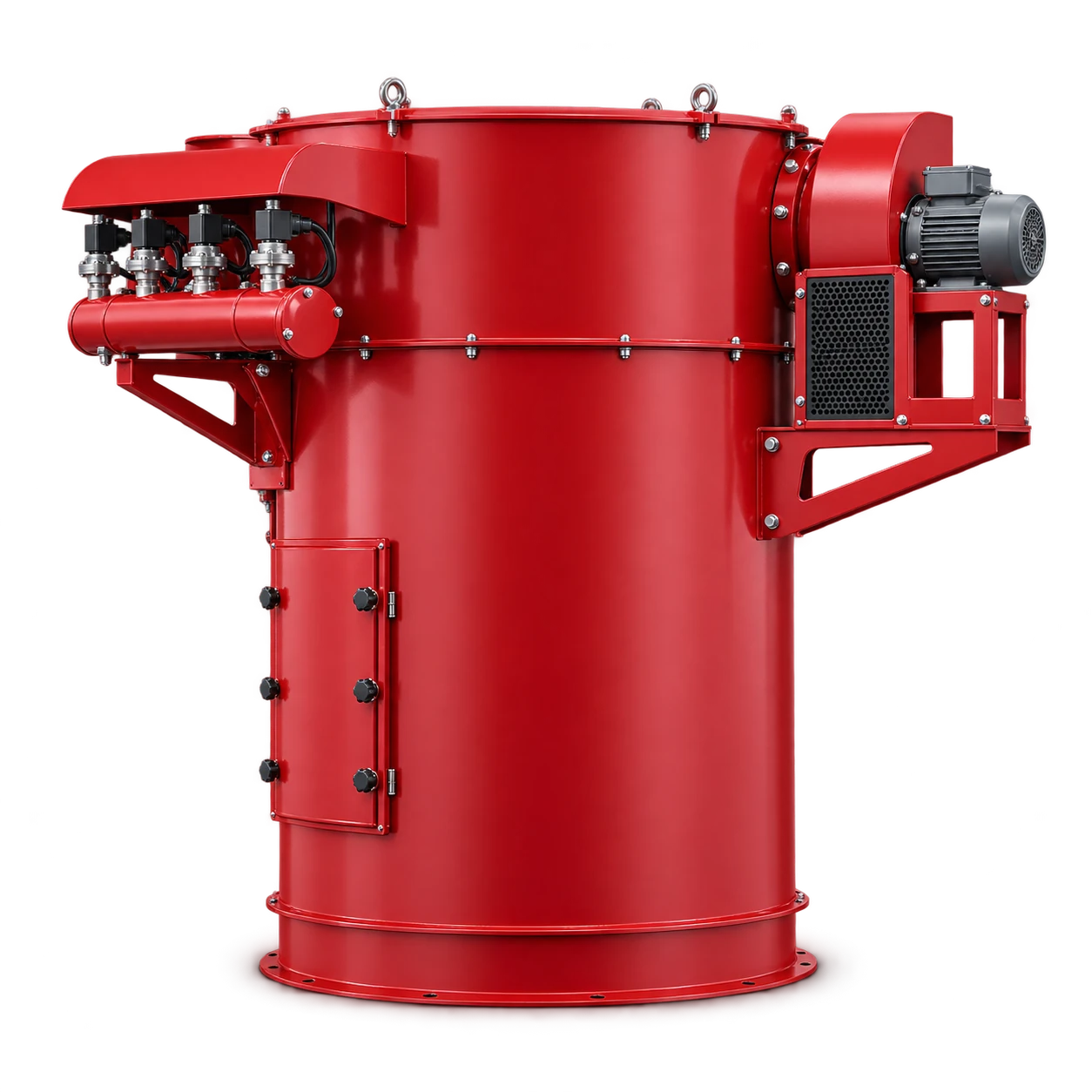
The DSC pulse-cleaned silo dust collector is cataloged as DSC20 and DSC30, with 20–30 m² filtration area. Selection uses airflow, filter area, silo capacity and cleaning duty. The catalog range does not provide a universal cleaning pressure or air consumption; request those values for the exact delivered configuration.
Separate three air systems before specifying the utility
Identify the dusty process airflow passing through the filter, the compressed air used for filter cleaning and any silo aeration air. These are different duties with different measurement bases. The cleaning supply may be high pressure while the silo itself is designed for low pressure. Never assign the compressor rating to the silo shell.
The Donaldson DFPRE installation manual specifies clean, dry, oil-free cleaning air and model-specific pressure and quantity. Its numeric limits apply to DFPRE, not DSC. Use that distinction when writing the RFQ: ask for exact requirements rather than transferring another collector’s settings.
The silo dust collector sizing guide covers the process-air and venting side. A correctly sized compressor does not prove adequate filter area, safe silo venting or explosion protection.
Request a cleaning-air data sheet
Make the collector supplier return the following information before sizing a compressor, dryer or branch line.
| Required data | Why it matters |
|---|---|
| Required pressure at the manifold | Defines the point-of-use duty, not compressor discharge pressure |
| Maximum permitted manifold pressure | Limits regulator and pressure-protection design |
| Air quantity per pulse and reference conditions | Allows a consistent average-demand calculation |
| Valve sequence and maximum pulse frequency | Defines peak and sustained cleaning demand |
| Permitted air quality and dew point | Defines filtration and drying for the environment |
| Connection, manifold and local storage details | Establishes the branch and receiver boundary |
| Controller mode and post-stop cleaning | Identifies demand outside production operation |
Specify whether a volume is free air at stated reference conditions or compressed volume at operating pressure. Do not add incompatible Nm³/h, actual m³/h and compressor free-air delivery figures. Ask for the conversion basis wherever a vendor uses “normal” or “standard” air without defining temperature and pressure.
For an existing line, log manifold pressure during the pulse sequence and during the plant’s largest simultaneous demand. Record regulator inlet pressure as well, so the supplier can distinguish inadequate supply from restriction in the branch or regulator.
Calculate average demand without hiding the pulse
An average air balance is Qaverage = air per pulse × pulses per minute. Sum all collectors on the same reference basis, then add other measured or documented users and explicitly justified allowances. This is a planning relationship, not a full compressor or receiver design.
Hypothetical example: assume a supplier reports 12 free-air litres per pulse at stated reference conditions, with six pulses per minute across the entire collector. Average cleaning demand is 12 × 6 = 72 L/min, or 0.072 m³/min. Two such collectors operating together require 144 L/min on that basis, before other demand. These are assumptions, not DSC consumption figures.
“Six pulses per minute” must mean the whole machine, not each of several valves. If it is a per-valve figure, the event count changes. Ask how differential-pressure control, continuous timer cleaning and post-stop cleaning affect the maximum duty. Do not size only from the low average observed with clean filters.
Check the pressure dip and recharge path
A pulse draws air over a short interval. Average flow can be modest while a restrictive hose or regulator prevents manifold recovery before the next event. Choose pipework, valves and filtration from the required dynamic performance, not merely a matching threaded connection.
The US Department of Energy compressed-air sourcebook describes local storage for intermittent demand and logging pressure and flow over time. A properly assessed local receiver can support short peaks; it cannot correct an inadequate sustained supply or bypass pressure-vessel requirements.
Give the air-system designer the pulse profile, minimum usable pressure, recharge interval, supply pressure and simultaneous loads. Require the receiver, drains, relief protection and installation to meet applicable local rules. Do not modify the collector manifold or use an improvised vessel as extra storage.
Specify dry air at the actual operating temperature
Select drying for the coldest exposed part of the supply route and the required pressure dew point. Ambient conditions at a warm compressor room may differ from an outdoor silo roof. Water condensed downstream of a dryer can defeat the original air-quality assumption.
Donaldson’s air-management guidance recommends point-of-use regulation, isolation and final condensate/particle control. State maintenance ownership for drains and filter elements. An oil-free compressor label alone does not prove the delivered air meets every cleanliness requirement.
Price the dryer, treatment, drains, branch, regulator and local storage separately in the utility proposal. Confirm that each item passes the required flow at the minimum supply pressure. Treat unlisted equipment as an open scope item, not an implied inclusion.
Prove the supply under the worst approved sequence
During commissioning, use the supplier-approved pressure and pulse settings. Record pressure before, during and after cleaning events, recovery before the next pulse, condensate control and leakage. Repeat with other expected plant users operating. Confirm the cleaning controller’s post-stop behavior without changing settings solely to make a short trial pass.
An acceptable test needs defined limits from the selected equipment documents. A manifold that recovers eventually but misses the next event is not evidence of adequate recharge. For filter-performance problems after air supply is verified, use the high differential-pressure diagnostic guide, which has a different fault-finding scope.
OSHA’s hazardous-energy guidance applies to service risks. Follow the site’s isolation procedure before opening the cleaning circuit; a stopped controller can leave pressure stored in the manifold.
Conclusion
Dust collector compressed air requirements belong in a returned utility specification: quality, dynamic manifold pressure, pulse quantity, sequence and simultaneous demand. Use an average balance to screen compressor duty, then verify pressure recovery and treatment at the point of use. Retain the installed test record and exact DSC cleaning data rather than adopting another manufacturer’s settings.