
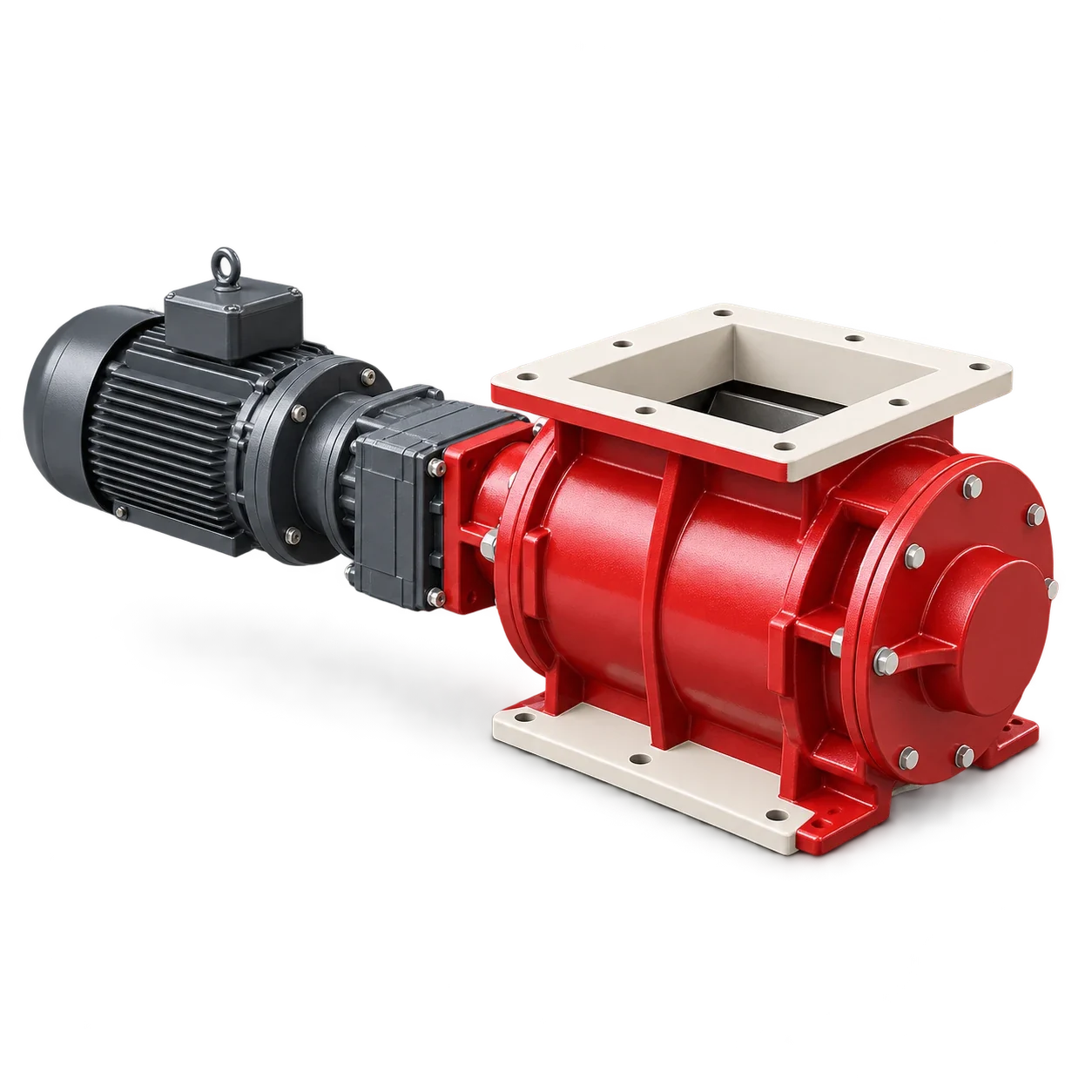
Rotary airlock leakage venting should be selected with the inlet vessel, conveying line and dust-handling system. First determine whether leakage actually impairs feeding or another specified requirement. If a vent is needed, define its destination and pressure conditions before sizing it. Adding an unqualified pipe connection is not evidence that the gas will leave by the intended route.
The YJD rotary airlock valve is cataloged for powder and granular-material discharge, with model and flange choices. Public displacement and speed data do not establish leakage at a particular pressure differential. They also do not establish that a vent port, pressure rating or protective function is included in a selected configuration.
Distinguish leakage paths before choosing a remedy
ACS Valves’ engineering explanation distinguishes gas passing through running clearances from gas carried back in rotor pockets. It describes body and transition vent options where the equipment supports them. These are possible arrangements, not a claim that every rotary valve has those connections.
Do not use rotor displacement as a leakage-air rating. A displacement value describes geometry; a leakage result must state its operating and measurement conditions. Likewise, “airlock” should not be interpreted as airtight isolation. Write the allowable behavior in terms of an actual system requirement, such as stable feeding or a defined inlet-vessel pressure, and have the responsible designer establish the limits.
Create a pressure and material interface record
Draw the material path and gas paths on the same arrangement drawing. Identify pressure-measurement locations, signs and reference conditions; a pressure without a location cannot support a vent decision. Separate the conveying line, valve inlet, proposed vent connection and vent destination.
| Interface record | Information to return | Decision it supports |
|---|---|---|
| Valve inlet and outlet | Normal and limiting pressures, temperature and operating states | Direction and range of differential pressure |
| Material feed | Required rate, density condition, particle characteristics and moisture | Whether the selected inlet and pockets can fill consistently |
| Valve configuration | Rotor, speed range, running-clearance basis and available ports | Applicability of the supplier’s leakage evidence |
| Vent destination | Vessel or collection system, pressure range and dust-handling provision | Whether gas has an acceptable receiving path |
| Connecting route | Elevation, length, fittings, restrictions and access | Pressure-loss and maintenance assessment |
| Control ownership | Instruments, alarms, permissives and response to abnormal states | Who prevents operation outside the agreed envelope |
Use the same pressure reference throughout the calculation and distinguish actual volumetric flow from flow normalized to declared reference conditions. Ask the supplier to identify empty, loaded, stationary or rotating test conditions. A curve for one state may be useful, but its relationship to the proposed operating states must be explained.
Decide whether venting belongs in this installation
SHAPA’s practical guide treats venting as a system-design decision and warns that it can sometimes impair flow or add an inlet restriction. Therefore, assess the arrangement before prescribing a vent on every installation.
| Observed or proposed condition | Design response to evaluate | Evidence before approval |
|---|---|---|
| Stable feeding within agreed pressure limits | Retain the justified arrangement | Representative operating record |
| Leakage interferes with inlet filling | Evaluate an approved body or transition vent | Supplier arrangement plus material-flow review |
| Destination pressure varies significantly | Review the complete gas path across operating states | Pressure-loss assessment and receiving-system capacity |
| No identified destination for gas and entrained dust | Hold the vent proposal | Defined containment and dust-handling interface |
Request leakage evidence before selecting the vent size
The valve supplier should return the leakage basis for the proposed configuration, its assumptions and the states not covered. The system designer should then document the connecting route and pressure losses against the receiving-system pressure range. A vent size copied from a similar valve does not show that this installation has sufficient driving pressure or receiving capacity.
Keep the material inlet geometry on the drawing. A transition selected for gas handling must still provide a suitable solids path and access for inspection. Confirm mechanical loads, supported pipework, seals and removal space. Do not drill a housing, alter clearances or add an unapproved port as an informal field modification.
Meyer Industrial’s troubleshooting guidance notes that temperature affects clearances and that pocket leakage changes with speed. Accordingly, obtain data for the actual temperature and speed envelope; a cold, stationary result alone is not a complete operating qualification.
Include abnormal states in the acceptance plan
The following is a proposed project-review checklist, not a universal interlock design. The responsible engineer must decide which states are credible and establish a safe test or documented review method. Do not create hazardous blockages to demonstrate a response.
| State to review | Required evidence |
|---|---|
| Start-up before steady material feed | Pressure and feed response within the approved sequence |
| Minimum and maximum approved feed duty | Stable inlet filling and documented gas-handling conditions |
| Receiving filter resistance increases | Defined response before pressure leaves the permitted envelope |
| Vent destination unavailable | Agreed prevention of unsafe operation or controlled shutdown |
| Temperature or material changes | Requalification trigger and named decision owner |
Set acceptance limits before the trial and record valve speed, inlet/outlet pressures, material condition, feed result and the state of the receiving system together. If performance changes, compare the complete record before blaming the valve or assuming a larger vent will solve it.
Keep process venting separate from protective functions
A leakage-air vent is a process connection, not automatically an explosion-relief device, isolation barrier or personnel-protection system. Any such function requires its own qualified design and documented applicability. The YJD catalog alone does not establish those approvals. Inspection and intervention must follow the plant’s authorized isolation and pressure-release procedure.
The rotary airlock quotation guide covers the broader purchasing package. Include the vent-interface record alongside it and assign responsibility for valve data, connecting ductwork, receiving-system capacity and commissioning acceptance. Leave unresolved items visible in the quotation instead of treating them as supplied by default.
Conclusion
Choose rotary-airlock leakage venting from a defined system requirement, a known gas destination and configuration-specific evidence. Verify normal and abnormal states with the inlet and receiving equipment included. That record supports a defensible valve-and-vent selection without a universal vent size or a zero-leakage claim.