
Start with effective belt tension from a recognized conveyor design method. Running pulley torque is that tension times pulley radius, and belt power is tension times belt speed. Starting selection then adds breakaway resistance, inertia and acceleration time and checks the result against traction, reducer duty, motor torque and the selected starter or variable-speed drive.
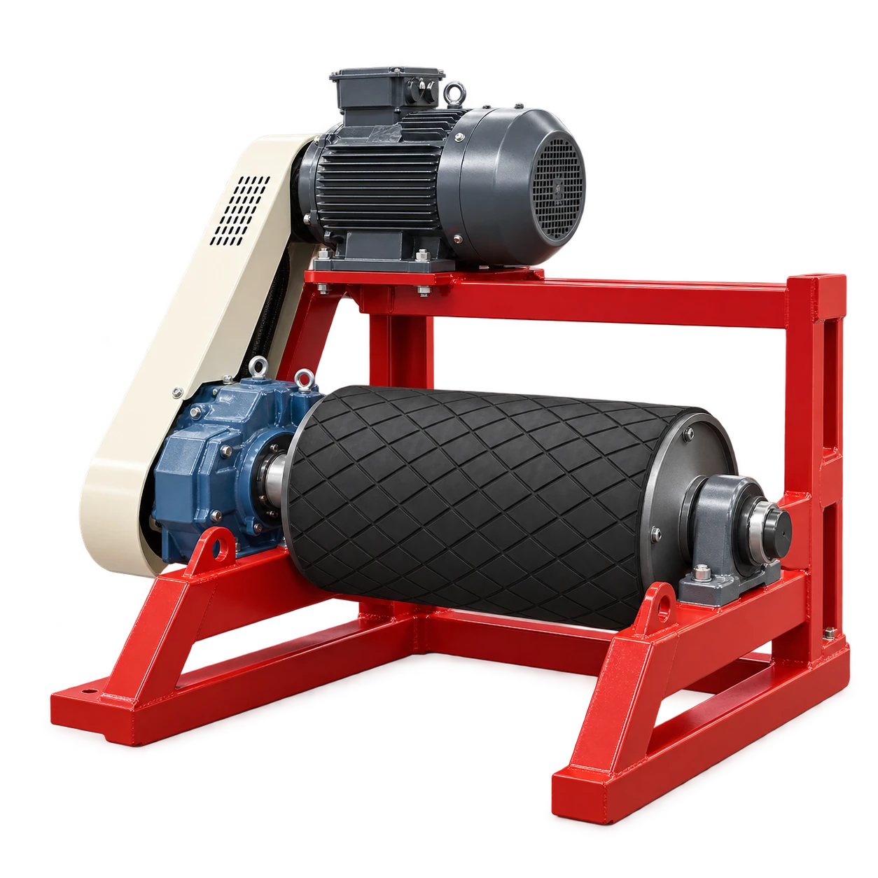
The VOGO belt conveyor drive frame integrates motor and shaft-mounted gearbox arrangements in listed 7.5–55 kW options. Those power choices do not replace a conveyor calculation. Supply the actual belt pull, speed, pulley, loaded-start case and mounting loads before selecting an option.
Establish the calculation boundary
Define the route, lift, belt and idler data, material load, loading resistance, skirt friction, cleaners, take-up, ambient conditions and operating modes. Include at least steady loaded running, loaded start, empty start, stopping and any rollback or regenerative case.
Rulmeca explains that effective tension (T_e) is the sum of forces needed to overcome friction, gravity and material acceleration. Its public page uses CEMA-derived methodology for standard continuous-flow conditions. Complex profiles, multiple drives, regenerative sections and unusual loading require the applicable full design method and qualified review.
| Input | Symbol | Required evidence |
|---|---|---|
| Effective belt tension | (T_e), N | Accepted conveyor calculation by operating case |
| Drive-pulley diameter | (D), m | Drawing including the design diameter basis |
| Belt speed | (v), m/s | Process and conveyor specification |
| Drive efficiency | (\eta) | Gearbox, coupling and manufacturer data |
| Starting tension or resistance | (T_{e,start}), N | Transient calculation, not a generic multiplier |
| Acceleration time and inertia | s, kg·m² | Control philosophy and referred system inertia |
| Tight/slack-side tensions | (T_1,T_2), N | Traction and belt-tension calculation |
Calculate running torque and power separately
At the drive pulley:
[ T_{pulley}=T_e\frac{D}{2} ]
[ P_{belt}=T_ev ]
Motor mechanical power must also account for drive losses: (P_{motor}=P_{belt}/\eta). Keep SI units: newtons, metres and seconds produce N·m and watts.
Worked example: a hypothetical drive case
Assume a completed conveyor calculation gives (T_e=12\text{ kN}), the pulley diameter is (D=0.50\text{ m}), and belt speed is (v=1.6\text{ m/s}). Then:
[ T_{pulley}=12000\times0.50/2=3000\text{ N·m} ]
[ P_{belt}=12000\times1.6=19.2\text{ kW} ]
If the assumed combined mechanical efficiency is 92%, the corresponding running demand is (19.2/0.92=20.9\text{ kW}). This does not select a catalog motor: service, thermal capacity, starts per hour and the actual efficiency data still apply.
Suppose the project’s transient analysis, rather than a rule of thumb, produces (T_{e,start}=18\text{ kN}). Starting pulley torque is then (18000\times0.50/2=4500\text{ N·m}). The designer must still check how that torque varies through acceleration and whether belt traction permits it.
Add acceleration and torque-speed checks
ABB’s drive-dimensioning guide treats the motor as a torque source and requires load, overload, thermal and drive-current checks. Acceleration depends on the difference between available motor torque and load torque over the speed range, together with referred inertia. A single ratio of starting torque to rated torque cannot capture that curve.
For a direct-on-line, softstarter or variable-speed start, obtain the motor and control torque-speed data. Define acceptable acceleration time, current limit and starts per hour. A long gentle ramp can reduce traction shock but may hold the motor and reducer in a high-torque, low-cooling condition; a short aggressive ramp may exceed belt traction or structural loads.
The belt conveyor drive quotation guide lists interfaces that belong in a supplier request. This calculation adds the numerical running and starting cases that make those interfaces reviewable.
Check traction, belt tension and hardware loads
Rulmeca’s catalog distinguishes effective pull from tight-side and slack-side tensions. The pulley radial load depends on (T_1+T_2), while the difference (T_1-T_2) provides effective pull. Verify wrap angle, lagging and take-up using the accepted method. Do not increase take-up tension merely to cure an undersized or poorly controlled drive; excessive tension raises belt, bearing, shaft and frame loads.
Check the reducer’s output torque, overhung or radial load, service factor, thermal rating, mounting position and backstop need. Check the coupling and key for transient torque. Confirm the drive frame and foundations for the actual belt reactions rather than motor mass alone.
Supplier return schedule
Require the supplier to return motor rated and available torque-speed curves, starting method and limits, reducer nominal and peak torque, service-factor basis, thermal duty, efficiency, acceleration time, starts per hour, pulley and shaft loads, traction assumptions, take-up condition, holdback or brake logic, and protection settings.
Record which values are calculated, assumed and guaranteed. Recheck if capacity, material density, belt speed, lift or starting mode changes.
Conclusion
Calculate running pulley torque from effective tension and radius and running power from tension and speed. Select the starting system only after adding breakaway resistance, inertia, acceleration time, traction and torque-speed behavior. The catalog drive frame is chosen from that complete duty, not from kW alone.