
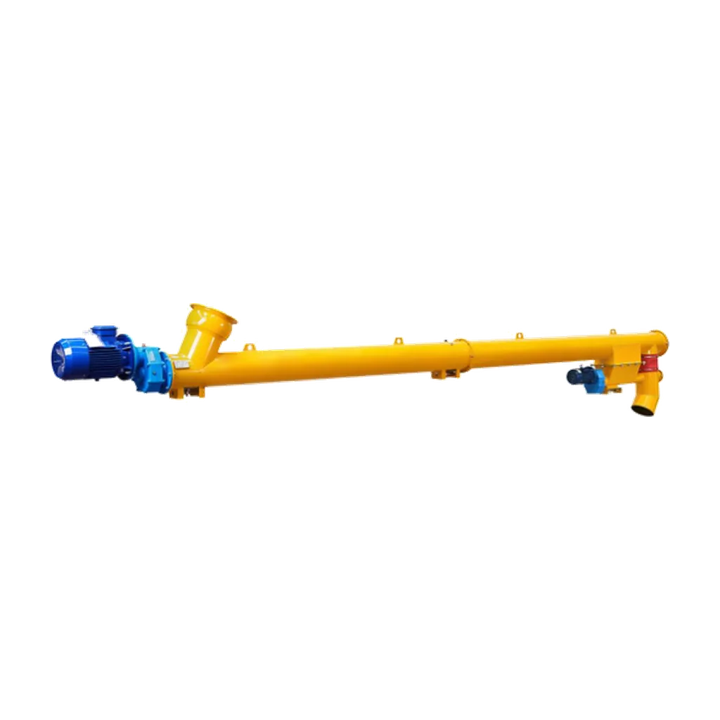
Cement screw conveyor VFD control is more than adding a speed knob. Define the allowed speed range, torque and cooling at low speed, startup and shutdown order, speed proof, overload response, downstream permissives and loaded-restart policy.
A VFD can be specified with VOGO’s project-configured tubular cement conveyors, subject to the motor, drive and process duty confirmed in the proposal.
Cement Screw Conveyor VFD Control Boundary
A control-fed conveyor receives limited flow; its VFD may trim conveying rate within a verified range. A flood-loaded screw under a silo is a feeder, so speed controls withdrawal and affects inlet loading and silo drawdown. That distinction changes both control logic and torque. The silo discharge article covers feeder geometry and head load.
Define Permissives and Trips
| Signal | Normal purpose | Required response |
|---|---|---|
| Downstream ready | Confirms receiving equipment and route | Block start or remove upstream feed |
| Drive ready | Confirms VFD has no active fault | Block command |
| Minimum speed | Proves material can be accepted | Permit upstream feed |
| Underspeed/zero speed | Detects lost rotation | Stop feed, then stop system safely |
| Sustained overcurrent | Indicates overload or restriction | Stop feed and trip at engineered threshold |
| High bearing/gear temperature | Detects mechanical degradation | Alarm or trip per supplier limit |
| Emergency stop | Handles risk-assessed emergency | Execute plant safety function |
The KWS engineering guide distinguishes speed sensors from zero-speed switches and notes their role in alerting or stopping a process. Select sensor location so a failed coupling cannot leave the sensor reporting motor motion while the screw is stationary.
Startup and Shutdown Sequence
A typical control-fed sequence is:
- Prove discharge gates and downstream equipment.
- Start the conveyor and accelerate to minimum permitted speed.
- Prove screw rotation.
- Enable upstream feed.
- On normal stop, remove feed and run the screw empty for an agreed time.
- Stop the screw after the emptying condition.
- On trip, remove feed immediately and preserve fault data.
The emptying time must be validated. It is not permission to run against a closed discharge. Inclined machines may retain or return material.
Check Low-Speed Torque and Cooling
The VFD, motor and reducer must deliver required shaft torque across the range. At low speed, self-cooled motors lose fan output; a long high-torque ramp can heat the motor. Use the selected Siemens SINAMICS manual for motor identification, overload functions, current limits and protective parameters.
Do not set current limit solely to avoid nuisance trips. The limit and delay must remain below the permitted reducer, coupling and shaft torque. Use the startup torque guide to establish that boundary.
Commission the Control Range
At minimum, normal and maximum speed, record delivered mass, motor current, speed feedback, bearing temperature, reducer temperature, leakage and downstream stability. Simulate loss of downstream-ready, speed signal and feed permissive without exposing personnel to moving equipment. Confirm fault codes and first-out indication.
OSHA requires conveyors to be rendered inoperable and tagged during hazardous repair, while 29 CFR 1910.147 requires isolation and verification before servicing. An HMI stop or VFD inhibit is not automatically an energy-isolating device.
Write a Cause-and-Effect Matrix
The controls narrative should state what happens for every relevant abnormal condition. “Trip conveyor” is incomplete because upstream feed, isolation gates, downstream equipment and restart permission also matter.
| Event | Immediate action | Restart condition |
|---|---|---|
| Downstream not ready | Block start or stop upstream feed | Downstream route proven |
| Screw underspeed | Remove feed and trip after validated delay | Cause cleared and speed sensor healthy |
| Sustained overcurrent | Remove feed; trip drive | Mechanical/process inspection completed |
| High bearing temperature | Alarm or trip per approved limit | Temperature and cause acceptable |
| VFD communication loss | Move to defined safe state | Communications and local status restored |
| Power recovery | No automatic loaded restart unless approved | Sequence and permissives re-established |
Use first-out fault recording so a cascade of alarms does not hide the initiating event.
Define Sensor Placement and Proof
A motor encoder proves motor motion. A target on the reducer output proves reducer motion. A target on the driven screw gives better evidence that the screw itself turns. Select the measurement point from the failure modes between motor and material.
Set underspeed delay long enough for normal acceleration but short enough to prevent continued feed into a stalled conveyor. Validate it from measured acceleration at cold and warm conditions, not an arbitrary timer. A high-current trip may operate faster than an underspeed trip; document priority.
Control a Planned Stop
For a normal control-fed stop, remove upstream feed first, maintain the downstream path, run the screw for the validated emptying time, then stop downstream equipment. If a level, weight or current signal is used to infer empty condition, define its failure behavior.
A feeder under a silo may not empty while its inlet remains exposed to material. Its stop sequence can require closing an isolation gate or accepting a loaded restart. Gate closure time and leakage matter. A screw does not isolate silo pressure or material by itself.
Manage Automatic Restart Risk
Following power return or fault reset, automatic restart can move machinery unexpectedly and feed a blocked downstream process. The risk assessment and applicable plant rules must define whether manual acknowledgement is required. Restoring a PLC output is not evidence that the physical route is safe.
Keep maintenance mode distinct from production mode. Jogging should require authorized local control, restricted duration and all protective conditions that remain necessary. It does not replace lockout/tagout for servicing.
VFD Commissioning Data Sheet
Record motor nameplate data, autotune method, control mode, current limit, torque limit, minimum and maximum frequency, acceleration/deceleration, skip frequencies, thermal model, cooling, speed-sensor thresholds and fieldbus-loss action. Capture current and actual shaft speed during empty, normal-load and loaded-restart tests.
If a low-frequency vibration appears, investigate mechanical resonance and alignment before applying a skip band. A skipped frequency can hide an operating problem or create a capacity gap. Any setting change after acceptance should be revision-controlled and rechecked against mechanical torque limits.
Handover and Change Control
The turnover package should include the cause-and-effect matrix, final VFD parameter backup, motor data, sensor locations, scaling, alarm and trip setpoints, test records and authorized reset procedure. Operators need the meaning of each first-out fault, not just a generic “drive fault.”
Protect parameter access by role. A field change to current limit, ramp, minimum speed or reverse permission can alter mechanical risk and must trigger engineering review and retest.
Cyber and Power-Quality Boundaries
A network command should not bypass hardwired or safety-rated functions defined by the risk assessment. Loss of communications must produce the documented state, while local isolation remains independent of software.
Record supply voltage, harmonics or regeneration concerns where relevant to the drive supplier. These electrical issues are separate from the mechanical torque calculation but can affect reliable operation and fault diagnosis.
Conclusion
Cement screw conveyor VFD control must coordinate process availability with mechanical limits. Define speed range, torque, cooling, permissives, speed proof, overload and shutdown logic before commissioning. Use measured performance to set the operating range, and never replace isolation or root-cause diagnosis with repeated reset or reverse commands.