
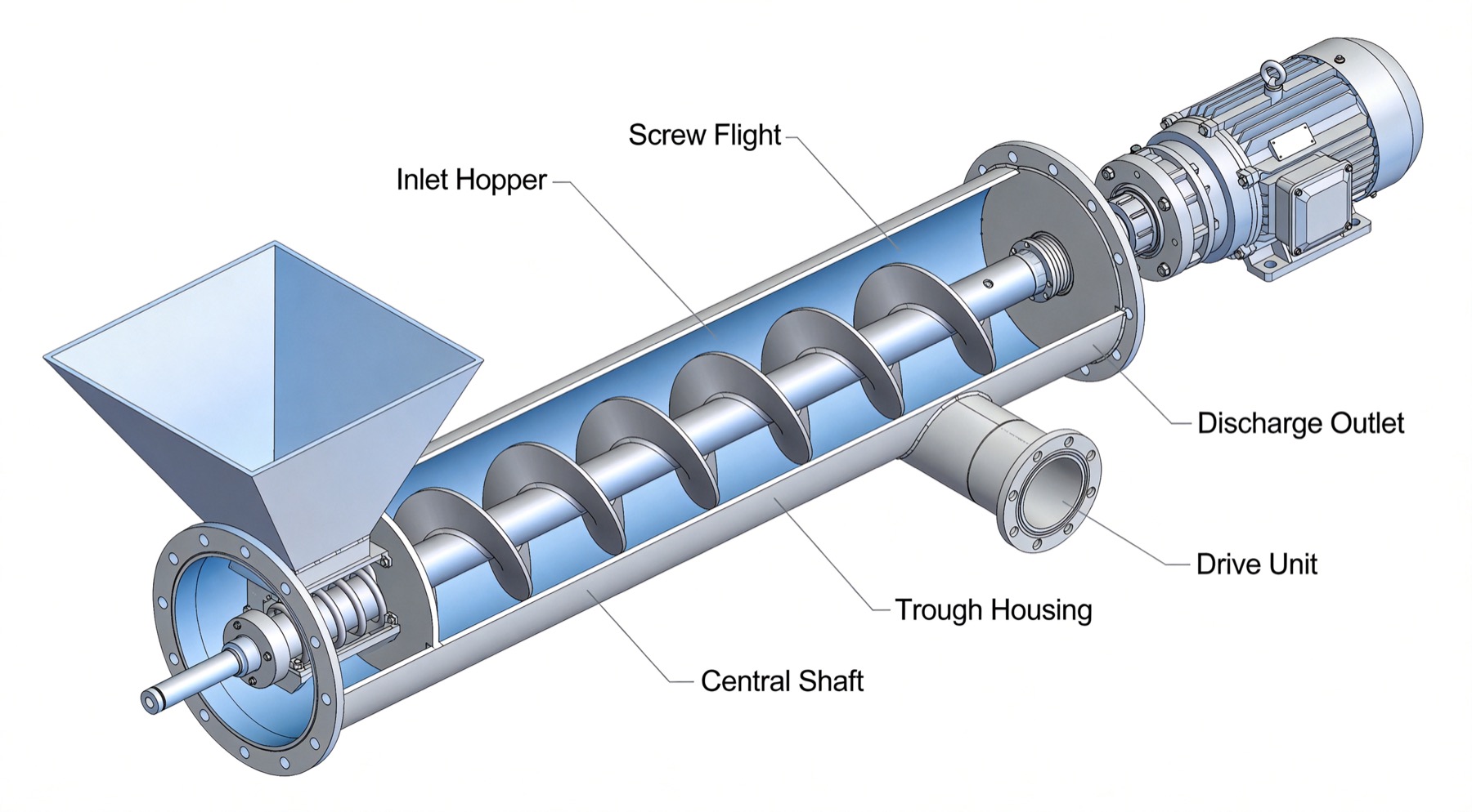
A cement screw conveyor wear inspection is useful only when it compares measured condition with an original baseline. Record flight thickness and outside diameter, housing or liner thickness, shaft journals, bearings, seals, current, vibration and leakage. Generic replacement percentages from another design are not adequate.
The component images on VOGO’s tubular cement screw conveyor page identify the main assemblies, while approved drawings and supplier limits govern the actual inspection points.
Separate Abrasion From Rubbing
Cement and mineral additions can abrade flight edges, housings and seals. Localized bright contact, one-sided wear or periodic noise points instead toward misalignment, a bent screw, support settlement or worn bearings. Moisture-related buildup can also force the flight against the casing.
| Pattern | Likely mechanism | Verification |
|---|---|---|
| Uniform flight-edge loss | Material abrasion | Compare thickness along the conveying path |
| One-sided casing polish | Misalignment or runout | Measure centerline and shaft runout |
| Severe inlet wear | High local loading or feeder duty | Confirm inlet classification and withdrawal design |
| Wear near hanger | Journal/bearing clearance or alignment | Measure bearing and coupling shaft |
| Seal track damage | Runout, dust or over-tight packing | Inspect shaft surface and seal adjustment |
KWS material-design guidance links abrasiveness and packing behavior to heavier construction and power. It does not supply a universal cement wear rate.
Cement Screw Conveyor Wear Inspection Measurement Map
Mark stations from inlet to discharge. At each shutdown, use the same instrument and location for:
- flight thickness at root and outer edge;
- remaining outside diameter;
- housing or replaceable liner thickness;
- radial clearance at defined clock positions;
- shaft-journal diameter and wear pattern;
- hanger and end-bearing clearance;
- coupling bolts, keys and weld indications;
- seal track, packing position and leaked material.
Record operating tonnes and hours since the previous inspection. A wear rate per 1,000 operating hours or per conveyed tonne is more useful than calendar age alone.
Decide Repair or Replacement
KWS’s repair example describes replacing damaged flights, repairing welds, renewing hardfacing and restoring straightness. Its stated tolerance belongs to that repair case, not every cement conveyor.
Use an engineering disposition:
- Compare measured dimensions with drawing minimums.
- Check whether section loss affects torque or fatigue capacity.
- Identify and correct the cause before adding new wear material.
- Define repair material, welding sequence and distortion control.
- Recheck straightness, runout, clearance and free rotation.
- Update mass or balance requirements if the design needs them.
- Reset the baseline and shorten the next inspection interval.
The KWS failure guidance connects worn bearings and shafts with misalignment and fatigue. A flight repair alone will not correct that chain.
Safe Internal Inspection
Stop feed, empty where practical, isolate every energy source, secure gates and stored material, verify zero energy, and control access. OSHA 29 CFR 1910.147 requires isolation and verification before servicing. The site must separately assess engulfment, confined-space and dust hazards.
The blockage troubleshooting guide helps connect wear evidence with overfill, restrictions and process changes. Use the cement screw conveyor maintenance checklist to place measurements in a repeatable outage record.
Establish Baseline Dimensions Before Service
The best wear record begins at commissioning. Preserve the approved manufacturing drawing, material certificates where supplied, flight thickness, housing or liner thickness, shaft diameters, clearances and runout. Photograph measurement locations and assign station numbers.
Measure with tools suitable for access and required accuracy. Ultrasonic thickness testing can be useful for housing or liner sections when the technique and calibration fit the material and geometry. Calipers or micrometers may suit accessible flight edges and journals. Use the same method each time or document the change.
Convert Measurements Into Remaining-Life Decisions
For each station:
Wear rate = dimension loss ÷ operating exposure
Exposure can be operating hours, conveyed tonnes or both. If a flight loses 1.2 mm over 2,000 hours, the observed average rate is 0.0006 mm/h. That arithmetic is an example, not a safe replacement forecast. Wear may accelerate after hardfacing is lost, clearance changes or cement condition changes.
Estimate the date at which the approved minimum could be reached, then schedule the next inspection well before it. Apply uncertainty for measurement repeatability and variable service. Never run to a calculated zero margin.
Link Wear to Operating Data
Dimension loss becomes more useful when paired with material source, additives, moisture, density, throughput, screw speed, start count and blockage events. A change in fly ash proportion or imported cement can change abrasion. Higher speed raises sliding distance per operating hour. Repeated partial blockages can force local contact.
Trend electrical current. Rising empty current after wear work may indicate distorted hardfacing or reduced clearance. Falling loaded current is not always good; severely worn flights can lose capacity and move less material.
Plan Hardfacing and Liner Strategy
Hardfacing can protect selected surfaces, but weld deposition changes heat input, mass distribution and clearance. Specify alloy, base-material compatibility, bead location, sequence, maximum distortion and final inspection. More hardfacing is not automatically better.
Replaceable liners can preserve the structural casing if fasteners and joints remain accessible and cannot loosen into the product. Inspect behind liners for trapped cement, corrosion or fretting where the design permits. A liner change that reduces internal diameter must be checked against flight clearance.
Repair Acceptance Checklist
Before reassembly, confirm:
- flight profile and minimum thickness;
- weld inspection required by the approved repair procedure;
- screw straightness and runout at specified stations;
- shaft-journal and coupling condition;
- casing or liner integrity and fasteners;
- calculated and measured clearances;
- mass balance requirements where relevant;
- isolated full-length hand rotation;
- empty current, vibration and temperature after startup;
- loaded capacity and leakage after controlled commissioning.
A repair that restores thickness but leaves a bent screw or worn bearing is incomplete.
Spare Strategy From the Wear Map
Stock parts based on measured lead time and failure consequence, not generic kits. A high-wear inlet flight, seal sleeve or hanger may justify a spare while low-wear casing sections do not. Preserve identification so a replacement matches diameter, handedness, pitch, shaft connection and material.
Use the wear map to refine the next purchase. If abrasion concentrates at one location, ask whether inlet distribution, speed, liner material or replaceable sections can reduce lifecycle cost without shifting failure elsewhere.
Report Findings by Severity
Classify each observation as monitor, plan repair, remove from service or engineering review. State measured value, approved limit, trend, uncertainty and consequence. Photographs without scale or orientation are supporting evidence, not the disposition.
When a limit is unavailable, stop short of inventing one. Obtain the original calculation or supplier assessment. Temporary operation, if considered, needs a documented risk and engineering decision, not a maintenance judgment alone.
Verify Capacity After Repair
Restored flight diameter or new liners change internal clearance and can alter capacity and power. Repeat the agreed empty and loaded baseline after repair. Compare actual mass flow at the same RPM and cement condition rather than judging only by appearance.
If current rises or rubbing appears, stop and inspect alignment and distortion. Do not “wear in” an interference condition under cement load.
Conclusion
A cement screw conveyor wear inspection should produce a dimensional trend, not a visual opinion. Measure repeatable stations, distinguish abrasion from mechanical rubbing, and base repair limits on the approved design. Correct alignment, bearings, process loading or sealing causes before rebuilding flights. Ask the supplier to approve the repair procedure and acceptance measurements.