
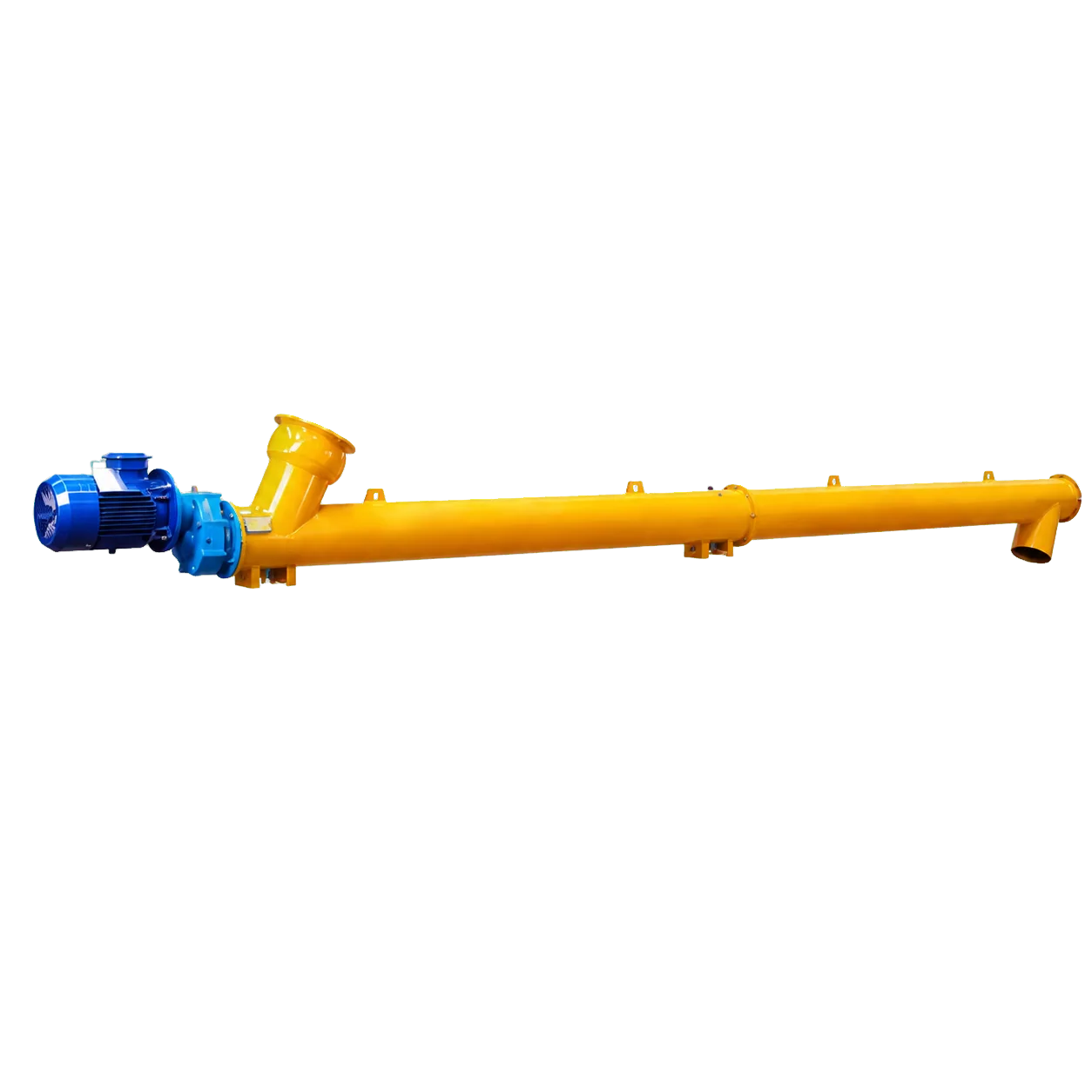
A screw conveyor motor power calculation for cement must include power to turn the empty machine and power to move material through the actual layout. Capacity alone is insufficient. Length, density, screw speed, bearings, seals, inclination, losses and restart duty can all change the selected motor.
The catalog range on VOGO’s cement screw conveyor configurations is a screening boundary. Final power and torque belong in the technical proposal.
Define the Calculation Boundary
If an upstream device limits flow, the screw is a control-fed conveyor. If its inlet remains covered under a silo and the screw controls withdrawal, it is a screw feeder. The latter includes head load and inlet shear; use the silo discharge design process, not a conveyor power worksheet.
Screw Conveyor Motor Power Calculation Structure
The KWS engineering method separates friction power, material power and drive losses. Its inputs include diameter factor, hanger-bearing factor, length, speed, volumetric capacity, density and material factor. ANSI/CEMA 350 is the wider industry reference. Use licensed tables or supplier calculations rather than reconstructed factors.
Total input power = (empty friction power + corrected material power + verified incline allowance) ÷ drive efficiency
The formula is a framework; every factor must be sourced for the selected design.
Worked Screening Example
A control-fed conveyor must deliver 12 t/h. Operating density ranges from 1.05 to 1.25 t/m³.
- 12 ÷ 1.25 = 9.6 m³/h
- 12 ÷ 1.05 = 11.43 m³/h
The low-density condition governs volume; the heavier condition still matters for load. Suppose a recognized method returns 0.8 kW empty friction, 3.7 kW corrected material power and 1.0 kW incline allowance at 90% drive efficiency:
(0.8 + 3.7 + 1.0) ÷ 0.90 = 6.11 kW
This example is not VOGO data and does not select a motor. Ambient derating, starts and torque still apply.
Convert Power to Torque
Torque (N·m) = 9550 × shaft power (kW) ÷ screw speed (rpm)
At 50 rpm, 6.11 kW equals 1,167 N·m. This steady value is not loaded-start torque. Settled cement, inclined fallback or a restriction may govern; use the startup torque guide.
| Input error | Consequence | Correction |
|---|---|---|
| One density | Understates either volume or load | State minimum and maximum credible density |
| Horizontal assumption | Omits lift and fallback | Use actual angle |
| Ignored bearings or seals | Understates friction | Define count and type |
| Efficiency guess | Distorts motor input | Use selected drive data |
| No upset case | Running motor may not restart | Register normal and restart loads |
Select the Drive as a System
After calculating shaft power, verify motor continuous rating, reducer output and peak torque, reducer thermal capacity, coupling and shaft torque, VFD overload, motor cooling, acceleration and zero-speed protection. SEW-EURODRIVE planning guidance shows why motor and gear-unit loading are related but separate.
Record material, density, capacity, length, angle, diameter, pitch, speed, loading, inlet type, bearings, seals, efficiency, starts, dwell and interlocks. Mark assumptions and sources. The capacity calculation guide covers the volume side; keep both worksheets linked.
Treat Incline Work Explicitly
For an inclined conveyor, the material gains potential energy. A useful physical cross-check is:
Ideal lift power (kW) = mass flow (kg/s) × 9.81 m/s² × vertical lift (m) ÷ 1000
At 12 t/h, mass flow is 3.33 kg/s. For a 4 m lift, ideal lift power is:
3.33 × 9.81 × 4 ÷ 1000 = 0.131 kW
This small number does not represent total conveyor power. It excludes internal sliding, fallback, flight and casing friction, bearings, seals, drive losses and upset loading. It is a reasonableness check: a calculated inclined contribution below the ideal lift work is impossible, while a much larger value needs its assumptions explained.
Avoid Double Counting and Missing Losses
Power worksheets often fail in two opposite ways. One method may already include bearing or material factors, and an engineer adds them again. Another method may calculate only theoretical displacement and omit mechanical friction. Keep a calculation map showing where each effect enters.
| Effect | Count once in | Verification |
|---|---|---|
| Empty screw and bearing friction | Friction power | No-load current after commissioning |
| Material sliding and internal friction | Material factor calculation | Loaded current and supplier method |
| Vertical lift | Incline method or explicit lift term | Geometry and mass-flow check |
| Reducer/transmission loss | Drive efficiency | Selected reducer data |
| Seal drag | Friction method or separate allowance | Empty current before/after adjustment |
| Restart and blockage | Torque cases, not continuous kW | Time-based torque trace |
Size for a Range, Not One Point
Run the calculation at minimum, normal and maximum throughput; minimum and maximum credible density; empty and loaded conditions; and minimum and maximum speed. A VFD-operated conveyor can have its highest motor thermal stress at a low speed with high torque, not necessarily at maximum throughput.
For intermittent duty, define the actual cycle. A high-power start every few minutes can govern motor and reducer thermal selection even if average throughput is modest. For continuous duty, ambient temperature and enclosure ventilation may govern.
Reconcile Calculation With Commissioning
Before material, measure phase current, shaft speed, voltage, power if available, bearing temperature and seal condition. Under controlled load, measure delivered mass and repeat the electrical readings. Compare measured input power with the predicted shaft power after accounting for motor and drive efficiency.
If measured empty power is high, investigate alignment, bearing preload, seal compression, rubbing and lubricant. If empty power agrees but loaded power is high, check density, moisture, overfeed, incline fallback and discharge restriction. Do not simply install a larger motor: additional available torque can transfer failure to the shaft or coupling.
Calculation Deliverables
The procurement package should include a calculation revision, source standard, input units, material range, load cases, selected motor, reducer ratio, screw RPM, efficiency, continuous torque, start torque and protective limit. Require the supplier to identify assumptions and margins. A one-line “motor = 7.5 kW” result is not auditable and cannot be safely reused when the layout changes.
Independent Review Questions
Before approval, ask whether the calculation uses mass or volume at each step, which density governs, whether the incline term is already included, how bearing and seal friction enter, what drive efficiency applies and which load case sets motor size. Confirm that shaft power and electrical input power are not confused.
Any change to length, angle, diameter, speed, bearing count, seal or material condition requires a revision. A previous project’s motor rating is not evidence for a modified layout.
State the Uncertainty
Material factors, density and upset fill are estimates until verified. Identify the range or conservative case used for each instead of presenting a calculated decimal as exact. Separate arithmetic precision from engineering confidence.
Commissioning measurements should close the loop. If the measured duty sits outside the assumed range, revise the calculation, protection settings and documentation rather than leaving an unexplained margin.
Conclusion
A defensible screw conveyor motor power calculation separates empty friction, material work, incline effects and drive losses, then checks startup torque independently. Use low density for volume and the heavy or settled condition for load. Do not apply the method to a flood-loaded feeder without a feeder-specific calculation. Submit the full calculation boundary for supplier confirmation.