A pulse-jet dust collector filter bag replacement should start with evidence of why the element failed and which element actually fits the collector. Do not buy by nominal length or fabric name alone. Record the collector model, tubesheet or cup interface, cage, media, finish, temperature and chemical exposure, grounding requirement, dust behavior and access arrangement, then ask every bidder to return deviations.
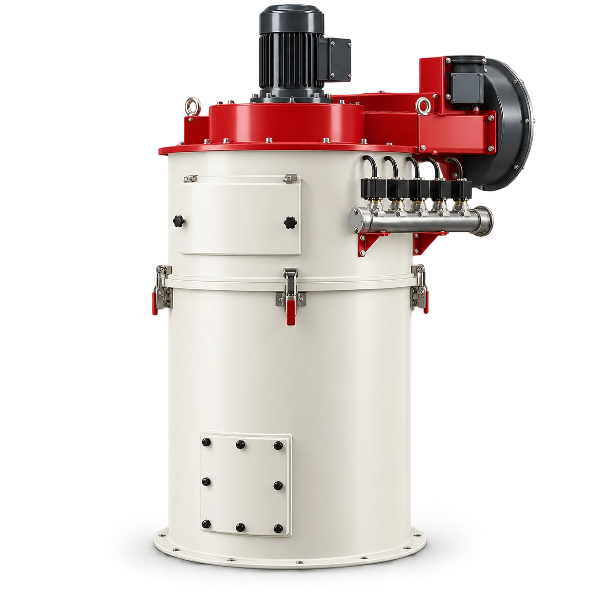
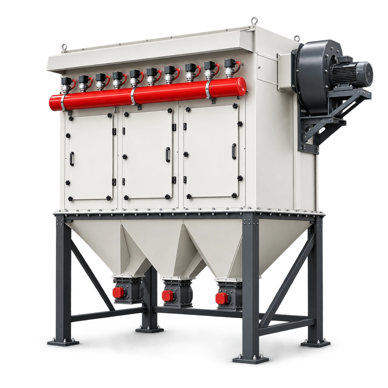
The DMC Series dust collector is a catalog family selected by filtration area, airflow, filter quantity and installation space. The listing does not publish a universal replacement interval or one filter bag for every DMC model. Confirm the current serial/model documentation and the physical interface before ordering.
Prove that replacement addresses the fault
High differential pressure can accompany blinded media, failed cleaning, inadequate compressed air, restricted discharge, excessive airflow, moisture or a changed dust load. Dust at the outlet can come from a torn element, a poor seal or another clean-side leak. Use the existing pulse-jet high differential pressure guide to isolate the operating cause; this page owns the replacement and release record after that diagnosis.
The U.S. EPA fabric-filter O&M manual recommends tracking failures and replacements because early failures can indicate installation or manufacturing defects, while repeated positions can reveal a local mechanism. Preserve the element position, visible damage, operating hours if known, pressure-drop trend and process condition. A discarded bag without that record removes useful evidence.
Freeze the approved element identity
Return a single data sheet for the old and proposed element. “Equivalent” requires evidence against the actual duty rather than a generic promise.
| Field | Buyer input | Supplier return |
|---|---|---|
| Geometry | Length, diameter, top and bottom attachment | Drawing and tolerances for offered element |
| Support | Cage shape, wire condition and venturi interface | Reuse/replacement decision and compatibility |
| Media | Fiber, weight and construction from approved records | Offered media and traceable designation |
| Surface treatment | Existing finish and process reason | Offered finish and stated limitation |
| Duty | Dust, temperature, moisture and chemical exposure | Compatibility statement for declared conditions |
| Static control | Grounding path required by project review | Conductive features and installation check |
| Quantity | Collector arrangement and planned spares | Supplied count, packaging and identification |
Do not infer temperature, chemical, fire or explosion suitability from the DMC image or the words “filter bag.” The facility hazard review owns those conditions. Changing media resistance can also change airflow and cleaning behavior; include the complete collector and fan operating point in the review.
Isolate, open and protect the clean side
Filter replacement can expose electrical, pneumatic, mechanical, gravity and dust hazards. OSHA’s hazardous-energy overview explains that unexpected startup and stored energy during servicing can cause serious injury. Use the employer’s authorized procedure: stop the process, isolate the fan and cleaning-air supply, prevent material entry and hopper discharge movement, dissipate stored pressure, verify the isolated state and control access.
Establish the site’s entry and respiratory-protection requirements before opening the housing. Prevent removed dust and dirty tools from contaminating the clean-air plenum. Package used elements according to the material assessment and local disposal rules; this article does not classify the collected dust.
Install by the collector-specific attachment
The AGI Airlanco pulse-jet manual shows why the installation method matters: top-access snap-band elements and bottom-access bag-and-cage assemblies use different attachments. It also directs lockout before troubleshooting. Use the current manual for the supplied collector rather than copying its dimensions or clamp instructions to a DMC unit.
Inspect the tubesheet or bag cup, cages, venturis and seals before inserting new media. Remove sharp edges and correct damaged support parts under approved repair instructions. Keep seams and grounding features in the required orientation. After installation, record each position and verify that attachments are fully seated without twisting, pinching or unapproved sealant.
Release the collector with evidence
Create a before/after record that can reject the repair:
- confirm every installed element and attachment against the approved list;
- remove tools and temporary covers, close access doors and verify gaskets;
- restore utilities using the site procedure and check cleaning-air leaks;
- start at the approved process condition and record airflow and differential pressure;
- inspect the clean side or use the approved leak-detection method;
- confirm hopper discharge, pulse sequence and alarms;
- retain the initial trend and inspect again at the site-defined interval.
New media may produce a different initial pressure drop. That change is not a universal pass value. Compare it with the design operating range, actual airflow and emissions or clean-side evidence. Do not change pulse timing merely to force a preferred gauge reading.
Conclusion
A defensible filter-bag replacement connects the observed failure to an exact element identity, safe installation and measurable release criteria. Request a complete supplier return for media and attachment, preserve every failed position, and accept the DMC collector only after the airflow, pressure-drop, sealing and clean-side checks agree with the approved operating plan.