
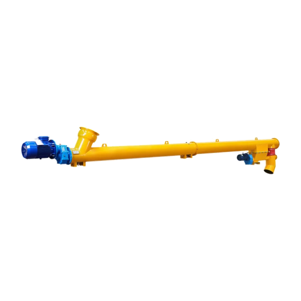
Fly ash is a supplementary cementitious material used in concrete and cement production. Recovered from coal combustion flue gases, it improves the workability and long-term strength of concrete while reducing the carbon footprint of cementitious mixes. Transferring this fine, dry powder from storage silos to weighing hoppers or mixing stages presents specific mechanical challenges. Unlike standard Portland cement, fly ash has distinct physical properties: high temperatures, high abrasiveness, and a strong tendency towards fluidisation. These properties degrade standard conveying equipment and cause excessive wear, fugitive dust emissions, and process instability.
Designing a reliable fly ash screw conveyor requires an engineering approach that addresses these handling challenges. Selecting and configuring screw conveyors for fly ash involves specific design considerations. Process engineers and mechanical designers must account for these factors to achieve efficient and safe plant operation. Applying these principles maintains continuous production and minimises unplanned maintenance downtime.
Understanding fly ash conveying characteristics
Designing an effective conveying system requires understanding the physical behaviour of fly ash. Fly ash is extremely fine, and its particle size distribution is much smaller than that of ordinary Portland cement. This fineness and low bulk density allow the material to aerate easily. During silo discharge or pneumatic transfer, introduced air causes fly ash to fluidise. In a screw conveyor, this fluidised state causes flooding. The material bypasses the conveying flights and flows uncontrollably towards the discharge end.
Fly ash also exits collection filters or silos at elevated temperatures that can exceed 100°C. The high heat, abrasive silica and alumina content, and fluidisation tendencies mean standard conveyor assumptions do not apply. Engineers must treat fly ash as a specialised material. Trough design, sealing arrangements, and drive configurations require specific modifications to prevent premature failure and maintain process control.
Moisture content varies depending on the collection method and storage conditions. This variation alters flowability and increases the risk of packing or blockages if the material absorbs ambient humidity. An analysis of the specific fly ash source is required before finalising the conveyor design.
Wear-resistant material and trough design
Fly ash is abrasive, so engineers must select suitable construction materials for the conveyor trough and screw flights. Standard mild steel wears through quickly during continuous fly ash service. This causes trough thinning, flight edge degradation, and structural failure. Designers can prevent this by specifying wear-resistant materials or applying hardening treatments. Trough liners made from high-chrome white iron or specialised abrasion-resistant steel plates extend service life. Designers should also harden the outer edges of the screw flights or fit them with replaceable wear tips.
Tubular screw conveyors are effective for fly ash. The rigid tubular body provides a fully enclosed conveying path. This limits external dust exposure and maintains structural integrity under the internal pressures that occur if the material fluidises. The enclosed design keeps the conveying path compact, which is useful in congested plant layouts with limited space.
When specifying the diameter and length, engineers must account for the specific bulk density and required throughput. This optimises trough loading to balance capacity with wear rates. Engineers must also consider the pitch of the screw flights. A variable pitch or specialised flight design manages material flow and reduces velocity at the trough walls to minimise abrasive wear. Designers should place regular inspection hatches so maintenance personnel can monitor flight thickness and trough condition without compromising the dust-tight integrity of the system.
Managing high temperatures and thermal expansion
Incoming fly ash is often hotter than ambient materials, creating thermal management issues. As the conveyor components heat up, the tubular trough and central screw shaft expand. Unaccommodated expansion causes mechanical binding, motor overload, and drive damage. Designers must calculate expected thermal growth using the maximum operating temperature and the conveyor centreline length. This determines whether to incorporate expansion joints in the trough or design the screw shaft with intentional clearances at the thrust bearing.
End bearings and hanger bearings also overheat from the conveyed material and the trough. Hot applications require bearings with high-temperature grease, integrated cooling jackets, or extended housings to maintain safe operating temperatures. Temperature control prevents mechanical seizure and protects shaft seals from heat degradation. If the incoming fly ash is extremely hot, engineers may need to add an inlet cooling section or use a water-cooled trough jacket to lower the material temperature before it travels the full conveyor length. These measures extend the life of rotating and stationary components.
Anti-fluidisation sealing and inlet control
Preventing fluidised fly ash from escaping the conveyor dictates the sealing design. Standard shaft seals often fail with materials that behave like aerated liquids. Engineers must select sealing solutions such as adjustable packing seals, air-purge seals, or specialised labyrinth seals to withstand the fine, abrasive powder and the slight internal pressures generated by fluidisation. Hanger bearings must minimise material accumulation and use self-lubricating or wear-resistant materials to prevent seizing.
Inlet control is also necessary. Because fluidised fly ash can flood the conveyor, relying solely on the screw’s volumetric capacity to control the feed rate is risky. A controlled feeding device upstream, such as a rotary airlock valve or a dedicated feeder screw, meters the material into the conveyor at a consistent rate. This prevents overfilling, which accelerates wear, increases power consumption, and causes blockages or motor overload. Inlet control keeps the screw operating within its designed trough loading parameters and stops the fluidised material from washing through the conveyor.
The discharge end must also handle the buildup of fine powder. This often requires flexible connections to isolate the conveyor from the receiving equipment and prevent seal damage from misalignment or vibration.
Conclusion
Designing a screw conveyor for fly ash requires accounting for the material’s abrasiveness, high temperatures, and strong fluidisation tendencies. Engineers achieve reliable powder transfer by selecting wear-resistant materials, accommodating thermal expansion, using anti-fluidisation seals, and controlling the inlet precisely. VOGO Machine supplies a Cement Screw Conveyor range configurable for specific duty requirements. These tubular screw conveyors have an enclosed design suited to cementitious powders, with selectable diameters of Ø89 mm to Ø407 mm and project-specific drive and bearing arrangements. Published capacity ranges are selection references; actual performance depends on material properties and operating conditions. Visit the VOGO Machine cement screw conveyor product page to review selection parameters and download the datasheet.
Conclusion
Selecting a screw conveyor for fly ash and similar cementitious powders depends on material properties, required capacity, and operating conditions. The VOGO Machine cement screw conveyor uses an enclosed, customisable design for dust-free bulk material handling. For selection parameters, technical specifications, and datasheets, visit the product page at https://vogomachine.com/cement-screw-conveyor/en/.