
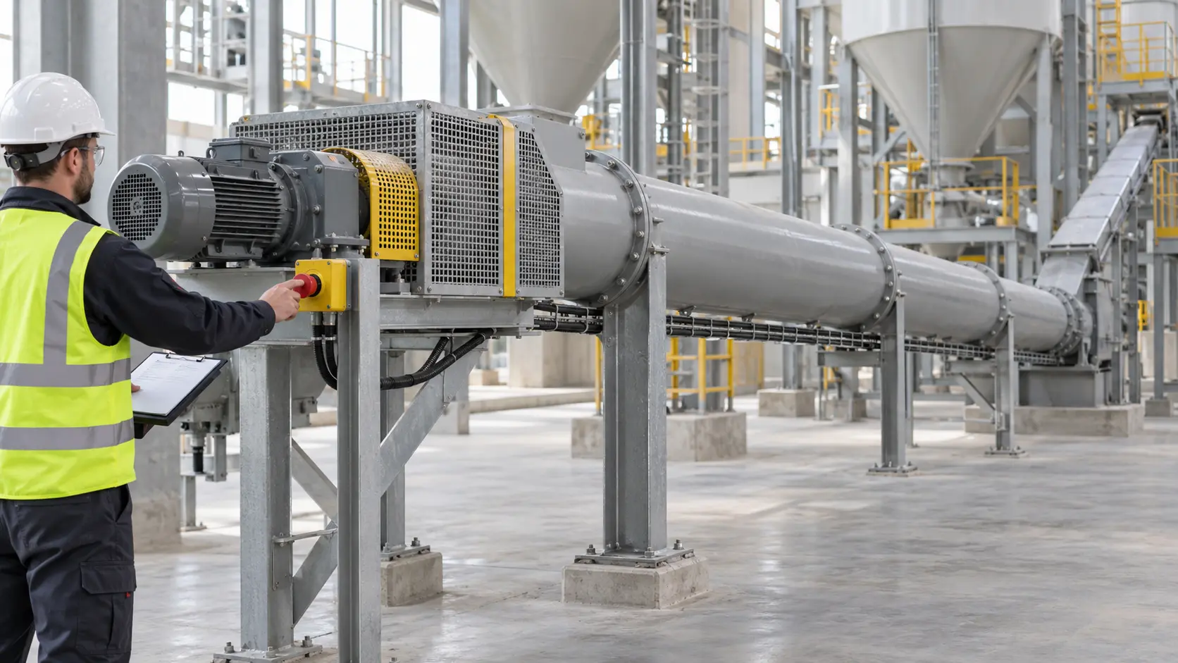
A cement screw conveyor emergency stop should bring the relevant hazardous motion and material feed to a safe state through a defined, tested sequence. Start by deciding which equipment is inside the emergency-stop span, which hazards remain after motion stops, where an operator can reach an actuator, and what must be proven before restart. A red button by itself is not a validated safety function.
For a project-configured cement screw conveyor, the motor, reducer, VFD, connections, instrumentation, and upstream and downstream interfaces depend on the approved project. VOGO’s public product information does not state that an emergency-stop circuit, safety performance level, stopping time, or site-specific sequence is included. Define those items in the machinery risk assessment, electrical design, cause-and-effect matrix, and acceptance plan.
Define the emergency-stop function before choosing hardware
ISO 13850:2015 specifies principles and functional requirements for emergency stopping independent of the energy type. It also makes an important boundary clear: reversal, motion limitation, shielding, braking, or energy disconnection may form part of a solution, but they are not automatically provided by the emergency-stop function. IEC 60204-1:2016 covers electrical, electronic, and programmable electronic equipment for machines, including coordinated groups of machines, and its Clause 9 scope includes emergency stop and power-drive-system functions.
Write a function statement before selecting pushbuttons, rope switches, relays, or PLC modules. It should name:
- the hazardous event the function is intended to reduce;
- every actuator and the work position it protects;
- the screw drive, upstream feed, gates, air systems, and downstream machines affected;
- the required stopping sequence and any controlled deceleration;
- the latched state, reset location, restart permissions, and fault response;
- the measurement method and acceptance criteria for the complete loop.
The emergency stop complements risk reduction; it does not replace a fixed coupling guard, an interlocked access cover, overload protection, or normal operating controls. The HSE machinery-safety guidance places fixed guards first where practical, calls for emergency-stop controls where necessary and within easy reach, and requires isolation or lock-off before blockage clearing, cleaning, or adjustment.
Set the stop span from process hazards
Stopping only the screw motor can be unsafe if an upstream rotary valve, pneumatic line, silo valve, or another feeder continues delivering material. Continued inflow may fill a stopped casing, aggravate a blockage, or leave a larger loaded-restart demand. Conversely, stopping every downstream machine instantly may remove the receiving path for material already falling through a chute. The safe span is therefore a process decision, not a default “stop all” rule.
Create a cause-and-effect table for each credible event. For an exposed drive hazard, the screw should stop. For an overfilled receiving hopper, the upstream feed may need to stop first while downstream equipment follows its approved sequence. For a dust-extraction fault, an immediate mechanical stop may or may not be the safest response; assess dust release, residual flow, braking behavior, and the permitted state of the collector. Document any device that intentionally remains energized and why.
Distinguish the inlet duty. A control-fed conveyor receives a limited rate from a separate device. A screw continuously covered by material beneath a hopper, bin, or silo performs screw-feeder duty, as explained in the KWS feeder-versus-conveyor distinction. An emergency stop can leave that feeder full under head load. Its design must consider the isolation valve, increasing or variable pitch, tapered outside diameter or justified mass-flow withdrawal arrangement, loaded-start torque, VFD low-speed torque, reducer service factor, and stall protection. A reduced-pitch inlet alone is not a complete withdrawal design, and a control-fed capacity table does not size the flooded section.
Place actuators where an operator can reach them safely
Map normal work positions, access routes, cleaning points, inspection points, drive and discharge areas, and any location from which a person may observe a developing hazard. An actuator should be recognizable, unobstructed, and reachable without crossing the hazard zone. Check the final installation rather than approving placement from a general arrangement drawing: platforms, stairs, handrails, panels, ducting, bags, and stored tools can alter access.
A mushroom-head pushbutton suits a fixed station. A properly engineered pull-cord arrangement may cover a long accessible run, but cord tension, slack detection, supports, corner routing, environmental exposure, and reset location must be specified and tested. Do not treat an ordinary process switch or a loose cable as an emergency-stop device. Prevent accidental operation through suitable placement and actuator design without making intentional operation difficult.
Place reset controls so the person resetting can assess the affected area or follow an approved visibility and communication procedure. Reset should release the latched command only. It should not start the screw, restart upstream feed, or defeat another active trip. Require a separate deliberate start after guards, permissives, material path, personnel clearance, and receiving equipment are verified.
Separate emergency stop, process trip, and isolation
These functions answer different questions.
| Function | Purpose | Typical result | What it does not prove |
|---|---|---|---|
| Normal stop | End routine operation in the planned sequence | Controlled feed cutoff and machine stop | Emergency response or energy isolation |
| Process trip | Protect equipment or process after a detected fault | Stop, alarm, or sequence action | Safety-rated performance unless specifically designed and validated |
| Emergency stop | Let a person avert or reduce an actual or impending hazard | Latched stop of the defined span | Safe access, disconnection, or removal of stored energy |
| Lockout/tagout | Control hazardous energy for servicing | Isolation, lock/tag, release or restraint, and verification | A rapid operational response to a developing event |
The US hazardous-energy rule in 29 CFR 1910.147 addresses servicing and maintenance where unexpected energization, startup, or release of stored energy could injure employees. For a screw conveyor, the boundary may include electrical supply, gravity-fed cement, silo head, pneumatic pressure, mechanical rotation, hot surfaces, and adjacent machines. An E-stop command, VFD inhibit, zero-speed display, or open contactor is not by itself lockout/tagout.
Measure the complete stopping response
Do not infer stopping performance from a PLC event bit or VFD “stop” status. Measure from physical actuator operation to cessation of the relevant hazard, including input response, safety logic, output device, drive response, coast or controlled deceleration, coupling and screw motion, and any delayed upstream flow. The acceptance limit must come from the risk assessment and system design; there is no universal safe stopping time for every cement screw conveyor.
Consider this commissioning example. A control-fed conveyor receives 30 t/h, equal to:
30,000 kg/h ÷ 3,600 s/h = 8.33 kg/s
If measured delay from emergency-stop operation until upstream feed actually ceases is 1.4 s, the feed delivered during that interval is approximately:
8.33 kg/s × 1.4 s = 11.7 kg
This illustrative value is not VOGO performance data and is not the total residual material. It excludes cement already in the chute and conveyor, material falling under gravity, instrument uncertainty, and any continued discharge during coast-down. The example shows why a command timestamp is inadequate: commission the physical system and confirm that the receiving volume, load path, and restart case tolerate measured residual flow.
Where a VFD performs controlled stopping, document the deceleration mode, torque capability, motor cooling, power-loss behavior, safe output architecture, and mechanical consequences. The VFD control guide covers process permissives and trip sequencing; do not assume a standard VFD stop command is a validated emergency-stop channel. Use shaft-level zero-speed monitoring as process evidence where appropriate, while keeping it separate from safety-rated standstill detection unless the complete function is designed for that purpose.
Prove the loop under realistic conditions
Test each actuator through the final control elements and observe the actual machine. A useful commissioning matrix includes:
- operate each pushbutton or pull-cord from its normal approach position;
- verify the intended screw, upstream feed, and downstream sequence;
- measure input response, feed cutoff, and final motion cessation;
- confirm the actuator latches and that every normal start command is rejected;
- reset from the approved location and confirm no motion starts automatically;
- apply a separate start only after all permissives are restored;
- test power loss and restoration, field-wire faults where the design provides diagnostics, and any bypass-management procedure;
- repeat representative no-load, loaded, and worst credible restart states without exposing personnel.
Record device tags, test conditions, instruments, measured times, results, witnesses, defects, corrections, and next proof-test date. Revalidate after a control-program change, drive replacement, change in braking method, line extension, upstream equipment change, or relocation of an actuator. The inspection-hatch safety guide explains the separate guarding, interlocking, and access-isolation decisions around covers and hatches.
An enclosed conveyor is not automatically airtight or pressure-rated. Emergency stopping also does not remove pressure, purge air, dust suspension, silo head, or a bridging hazard. A screw cannot independently cure arching, rat-holing, or bridging; outlet geometry, cement moisture and consolidation, flow regime, aeration, isolation valve, and flow aids remain system factors.
Conclusion
A cement screw conveyor emergency stop is credible only when its hazard, equipment span, sequence, actuator access, reset behavior, stopping response, and proof test are defined together. Stop upstream inflow when the assessed hazard requires it, preserve any downstream function needed for a safe material path, measure actual motion and residual flow, and prevent reset from causing an automatic restart. Treat a flood-loaded unit as a screw feeder, and apply verified lockout/tagout before access regardless of the emergency-stop state.
Send VOGO the process cause-and-effect matrix, machine interfaces, operating cases, safety requirements, and acceptance plan when requesting a project review.