
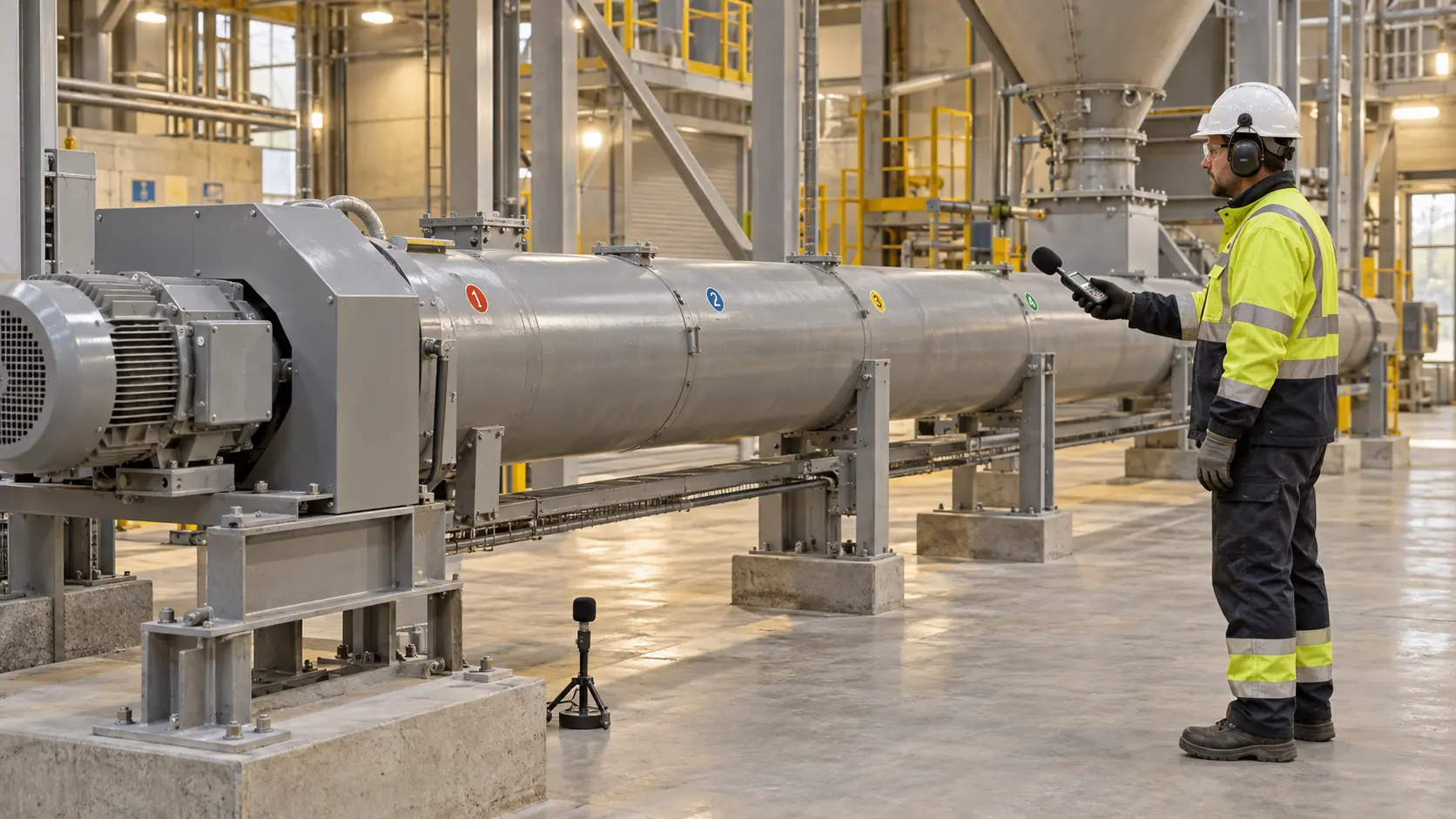
Cement screw conveyor noise troubleshooting starts with a repeatable comparison, not a guess based on loudness. Measure at fixed external points, document the operating state, compare background, empty, and representative loaded runs, and relate any change to screw speed, motor speed, material flow, vibration, current, and temperature. A new sound can locate a fault family; it rarely proves the root cause by itself.
On a project-configured tubular cement screw conveyor, diameter, speed, supports, bearings, seals, drive, duty, and instrumentation are selected for the application. VOGO’s public product data does not state a guaranteed sound level, supplied sound-monitoring package, acoustic enclosure rating, or universal noise acceptance limit. Put those requirements in the project specification when they matter.
Define the noise question before measuring
Three common tasks need different methods:
- Condition troubleshooting asks whether the machine has changed and where the source is likely to be.
- Machinery emission testing determines sound pressure at specified workstations or other defined positions under a declared test method.
- Worker exposure assessment evaluates a person’s accumulated exposure across tasks and time, not just one conveyor reading.
ISO 11201:2010 covers machinery emission sound-pressure measurements at workstations and other specified positions in an essentially free field over a reflecting plane. It requires attention to background and environmental corrections and can produce engineering- or precision-grade results. A troubleshooting route inside a live cement plant may not reproduce that acoustic environment, so label it as a condition trend unless the full standard method is met.
For occupational context, NIOSH recommends an 85 dBA eight-hour exposure limit using a 3 dB exchange rate, where each 3 dB increase halves the recommended exposure duration. That is a worker-exposure recommendation, not a universal pass/fail limit for the machine or proof of its mechanical condition. Applicable legal criteria depend on jurisdiction and the actual exposure assessment.
Build a repeatable cement screw conveyor noise route
Keep every coupling, shaft, fan, and access opening guarded while collecting operational data. Mark external measurement points on the stationary motor frame, gearbox area, drive-end bearing housing, casing sections, intermediate support locations, and tail end. Do not place a microphone, cable, hand, or probe through a guard.
At each point, record:
- meter type, serial number, calibration check, weighting, time response, and frequency-band setting;
- microphone position, distance, height, orientation, and nearby reflecting surfaces;
- background sound and which neighboring machines are running;
- screw rpm, motor rpm or drive frequency, direction, and elapsed run time;
- empty or loaded state, material identity, estimated rate, inlet condition, and discharge condition;
- motor current, bearing temperature, vibration observation, weather or ventilation changes, and operator notes.
Use the same route for the accepted baseline and later checks. A calibrated integrating sound level meter can provide A-weighted equivalent level for overall comparison. C-weighted peak may help document impulsive events. One-third-octave or narrowband data can help separate source families, provided the instrument and analyst are suitable. A phone app can flag an apparent change but should not support a contractual or compliance decision without validated hardware, calibration, method, and uncertainty.
The HSE noise guidance directs employers and manufacturers toward controlling noise risk and includes examples involving conveying and damping. Hearing protection may still be necessary, but it does not repair a rubbing flight, loose panel, damaged bearing, or resonant support.
Test operating states without hiding the source
Start with the conveyor stopped and nearby plant running normally to capture background. Then compare, under an approved commissioning or troubleshooting plan:
- nearby plant off where practicable;
- conveyor running empty at normal speed;
- representative loaded operation at a stable material rate;
- defined speed steps if the drive and mechanical design permit them;
- coastdown observations from a safe external position;
- post-repair repetition of the same accepted states.
Do not disconnect a coupling, jog in reverse, bypass an interlock, or run with a guard removed merely to improve diagnosis. Such tests require an engineered procedure and controlled area. The reverse-rotation safety guide explains why reverse jogging is not a generic clearing method.
A control-fed conveyor receives a regulated upstream flow. A screw continuously flood-loaded below a hopper, bin, or silo is a screw feeder. Feeder head load, inlet geometry, full-load starting torque, VFD low-speed torque, reducer service factor, and stall protection alter the acoustic and load signature. Do not compare a feeder loaded-start recording with a control-fed empty conveyor baseline or apply a normal conveyor capacity table to that duty.
Use speed orders as clues, not verdicts
Convert rotational speed to frequency:
Rotational frequency (Hz) = rotational speed (rpm) / 60
In an illustrative system, a screw at 60 rpm produces a 1.0 Hz shaft order, while a motor at 1,450 rpm produces about 24.2 Hz. A repeated knock synchronized with the 1 Hz order points the investigation toward a once-per-screw-revolution event: a bent section, periodic casing contact, coupling issue, or localized buildup. A tonal change following motor speed is more likely on the motor or gearbox side. Gear-mesh, bearing, and structural frequencies require actual tooth counts, bearing geometry, and vibration or acoustic analysis; do not infer them from sound alone.
Decibels are logarithmic. If an unchanged measurement route rises from 78 to 84 dBA, the difference is 6 dB. The corresponding sound-energy ratio is:
Energy ratio = 10^(6/10) = 3.98
That is roughly four times the sound energy at the measurement point. It is not four times the perceived loudness, four times the wear, or proof of a specific defect. First confirm matching background, load, speed, microphone position, and reflections.
Match the sound pattern to corroborating evidence
| Sound or pattern | Check while guarded | Isolated inspection targets |
|---|---|---|
| Sharp scrape or squeal from one casing section | Current, vibration, speed dependence, thermal state | Flight clearance, buildup, liner, bent screw, support movement, thermal growth |
| Knock once per screw revolution | Shaft-order timing, casing location, load sensitivity | Coupling, shaft straightness, displaced flight, foreign object, localized contact |
| Rumble or irregular sound near a bearing | Housing temperature and vibration trend | Lubrication, contamination, fit, seal drag, internal damage, alignment |
| Gearbox whine that tracks motor speed | Drive frequency, oil temperature, vibration spectrum | Gear mesh, bearings, oil condition, mounting, alignment |
| Hiss or whistle at a seal or joint | Local pressure direction, purge state, dust trace | Seal condition, purge setting, gasket, flange, venting boundary |
| Material roar only at higher rate | Feed rate, filling, discharge, current | Impact point, fallback, buildup, aeration, outlet restriction |
| Broad rattle at one speed band | Run-up/coastdown response, support vibration | Loose cover or guard, structural resonance, foundation or support looseness |
The SKF bearing failure guide treats noise, vibration, and temperature as related condition indicators. It notes that grinding, squeaking, and other irregular bearing sounds indicate poor condition or another problem, while contamination, incorrect fits, looseness, and damage can all increase noise. That breadth is the reason not to replace a bearing from a sound recording alone.
Use the vibration troubleshooting route to test speed-related mechanical clues. Compare the motor-current baseline for added load, and use the bearing-temperature method for local thermal evidence. Agreement among independent signals is stronger than any single symptom.
Decide when to stop and isolate
Initiate the approved controlled stop when noise changes suddenly or is accompanied by metal-on-metal scraping, repeated heavy impact, rising current, abnormal vibration, heat, smoke, dust release, guard movement, loose supports, or discharge loss. Stop upstream feed in the defined sequence. Do not stand beside a suspected failure waiting for a better recording.
Before removing any cover or guard, touching a housing, clearing material, or turning the screw manually, isolate hazardous energy under the site procedure. OSHA’s hazardous-energy guidance explains that unexpected energization, startup, or release of stored energy during servicing can cause serious injury. Address electrical power, stored rotation, gravity, upstream material, silo head, pneumatic or hydraulic energy, pressure, and hot surfaces. An emergency stop, VFD stop command, zero-speed indication, or quiet machine is not by itself isolation.
The screw casing may attenuate some sound, but enclosed does not mean acoustically rated, airtight, or pressure-rated. Adding lagging or an acoustic jacket can trap heat, obstruct inspection, load flexible connections, or conceal leakage. Review temperature, fire behavior, hygiene, maintenance access, pressure, and support loads before applying any treatment.
Verify the repair with the same route
Record the fault hypothesis, evidence, isolated findings, repair, parts, alignment or clearance results, and test conditions. Repeat the original background, empty, and loaded measurements at the same points. Accept the repair only when the abnormal pattern is removed or returned to the approved baseline and current, vibration, temperature, guarding, containment, and process performance also pass.
Do not declare success because one overall dBA value fell. A loose panel may stop rattling while a bearing trend remains abnormal; an acoustic jacket can reduce the reading without correcting contact. Keep the raw spectra or band data, photos of measurement positions, instrument calibration record, and operating log with the maintenance history.
Conclusion
Cement screw conveyor noise troubleshooting is reliable when the route, instrument, operating state, and background are controlled. Separate exposure, emission, and condition questions; compare fixed points under matched empty and loaded states; use rotational frequencies only as clues; and confirm the diagnosis with current, vibration, temperature, and isolated inspection. Stop promptly for scraping, impact, heat, smoke, guard movement, or simultaneous load changes, and never open the machine until hazardous energy and stored material are controlled.
For a project noise review, send VOGO the conveyor layout, duty cases, drive data, measurement route, baseline records, spectra, and required acceptance method.